Grendels lighting Tutorials

I am pretty sure you had something wrong with that capacitor. I have used that value before without a double blink to it. But if not, then I can see that would be useful!

I still have not had time to get up to my hobby room and check this out. I will try to on Saturday.
 
Here's the value I originally had: R2 and R3 were 500k potentiometer, R1 was a 470k (I think), the capacitor was a 10 micro farad electrolyte capacitor and finally the 555 chip. As for the wiring, from what I remember, pin 1 to ground, pin 2 to capacitor to ground and to pin 6, pin 3 to R1 to LED to ground, pin 4 to power, pin 5 nothing, pin 6 to R2 to pin 7, pin 7 to R3 to power and pin 8 to power.

Cheers
 
I'm digging these tutorials! I've been playing around with the 4060 chip and having a ball coming up with differerent blink rates. My only trouble is converting what i have on the breadboard to a board i can put in the model. do you have a digram for the completed 4060 board i can use to make my finished board?
 
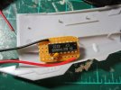
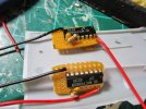
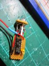
Here are a few photos from the Mercury 9:

IMG_0730.jpg

IMG_0731.jpgIMG_0736.jpg

Don't know if that helps at all. It is pretty much the same as what you put on the bread board.
 
I have made blinky lights! Just had to tell someone!

I know it's the easiest circuit in the world, one 4060 and one resistor and capacitor but I don't care, I made it.

Thanks Grendel for your channel and your helpful thread here. It's inspired me to light a Revell Klingon D7.
 
Great!!!!

It doesn't matter that it is the easiest in the world, you did it on your own and now you can try harder circuits....
 
Grendels said:
Great!!!!

It doesn't matter that it is the easiest in the world, you did it on your own and now you can try harder circuits....

And it was great fun.

Is it ok to ask a couple of questions in here?
 
Grendels said:
yes it is but I might be a bit slow answering. it depends on my workload

No rush at all, honestly. Thank you for taking the time.

I think my major query is can I damage the chip by using too low or high resistors or capacitors? Or is it pretty much bomb proof what I stick on it?

And is it just the one side that I can stick LEDS on?

Thanks again.
 
There are a few things that will kill these chips.

  • Heat
  • voltage: Keep it between 5V and 15V
  • Current: Don't plug it straight into a wall
  • Polarity: Make sure the + and - are correct

The resistor and capacitor should not affect the chip at all. They are just used for timing.

And you can stick the LED's on either side of the chip. Set one up on a bread board, and just play around with it. If the pins don't work, flip the polarity of the LED. If it still doesn't work, well then, don't use those pins. It won't fry the LED.
 
So many helpful tips thanks for this Grendels. It will help me on my future builds couse i think i am gonna take a brake on building planes soon and build some Sci-Fi models.
 
G'Day Grendels,

need some guidance ...

lighting the Marquis ship from Star Trek Voyager.

Using a 9Volt battery as the source.
4060 timing chip with 4 led's with fibre optic
18 led's to light engine and grill areas. 10 water clear blues and 8 water clear reds.

I've been using the linera1.wiz for resistor value and wiring everything in parallel.

i'm now lost on how to figure out
1. if the 9 Volt is enough, and should have a second for the 4060
2. am i over driving this thing ?
3. appears to have some flickering on the LED's not in the 4060 circuit, but i think that is due to the power draw on the circuit.
4. Should I be looking at 2 batteries in series to power the circuit - 18Volts total ...
5. I can't figure out the battery life ...

At present, i'm trying to keep to 1 power source with an external connection to the battery, so if i decide later down the track to use a wall wart, i can rewire the base.


Any ideas ?

thanks
 
You are definitely running too many LED's on one 9V battery. At the most one 9V battery can supply 310 maH, or milliamp hours.

Each LED consumes 20 ma, so if you have 15 LED's your 9V battery can run them for one hour. You are running 22 so you take 310/(20*22)=0.7 or 42 minutes, and this does not take into account the 4060 chip. So I suspect you are trying to pull more current out of one 9V battery than it can handle.

There is one solution so you don't have to rewire the whole thing, use two 9V batteries in parallel. This will keep the voltage at 9V and double the lifetime of the batteries.

This is one of the reasons I don't use 9V batteries with model building, they just don't last long. One AA battery has 1300 mah. Which will last quite a bit longer than the 9V.

As for the flickering, the 4060 might be leaking some of it's signal to the rest of the circuit. One way to fix this is with a diode connected to the power side of the 4060 I have seen this before.

Also I have found out that 4060's can't work with more than 4 LED's. So you should be fine there.
 
thanks mate - i was about to solder it all together - so i can redo all the resistors ...

i'll try for 6V - 4 AA's
 
Hey G... have you used any of the self flashing LEDs from Evan's Designs yet? Something I've found in lighting my kits is that they are great for making random flashing patterns for consoles and the like, and if you need a set flash rate for several, just hook one up to a few fiber optics. They are pretty easy to use and work with. They are all presoldered with resistors and 28 gage wires. Can get them in sizes ranging from Jumbo to Pico size.
 

Latest posts

Back
Top