nicholassagan
sippin on gin + juice
- Joined
- Dec 28, 2011
- Messages
- 2,013
I was itching to get some real progress done on some of the commission work on my bench so I started with this one. It’s the Allegiance-class Heavy Star Destroyer first seen in the background in the Dark Empire comic series. (See here and here). My client asked for it in 12″ scale, but since this build will utilize parts I pre-fabricated for a different project, it will end up being closer to 13″ or 14″. The math works out to be somewhere around 1/7200. I’ll also be designing a blueprint-style laser cut plaque for the base. Detail wise, the majority of the plans are derived from FractalSponge’s rendering (see here). Some details, such as the domes, conning tower, turbo-laser turrets and ion cannons will be 3D printed.

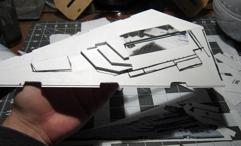
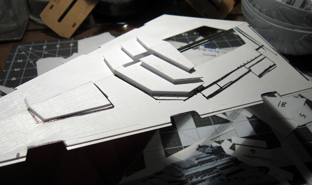
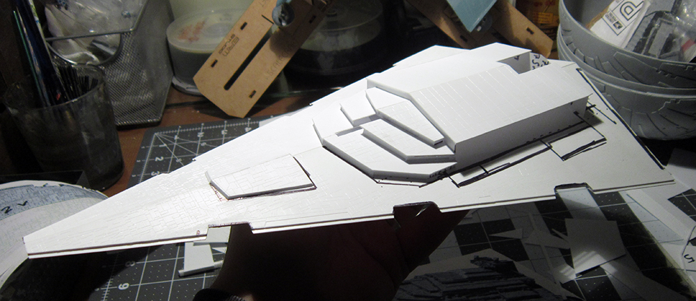
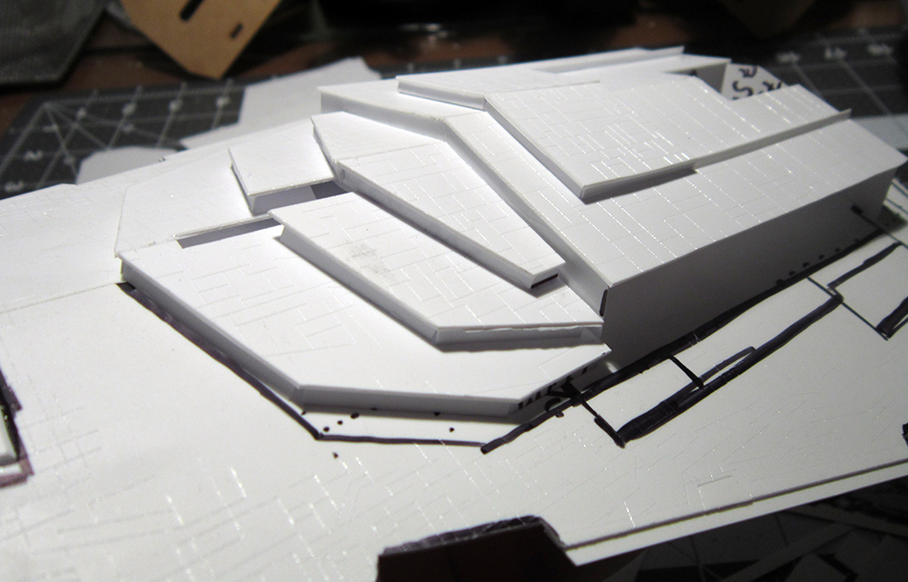
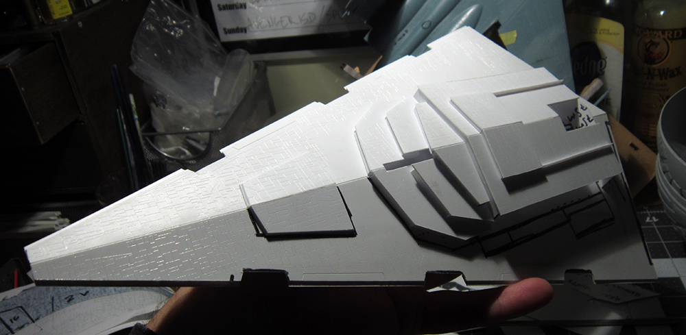
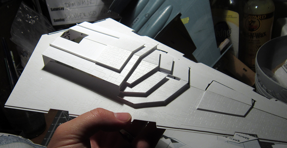
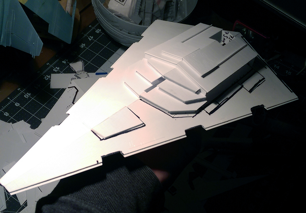
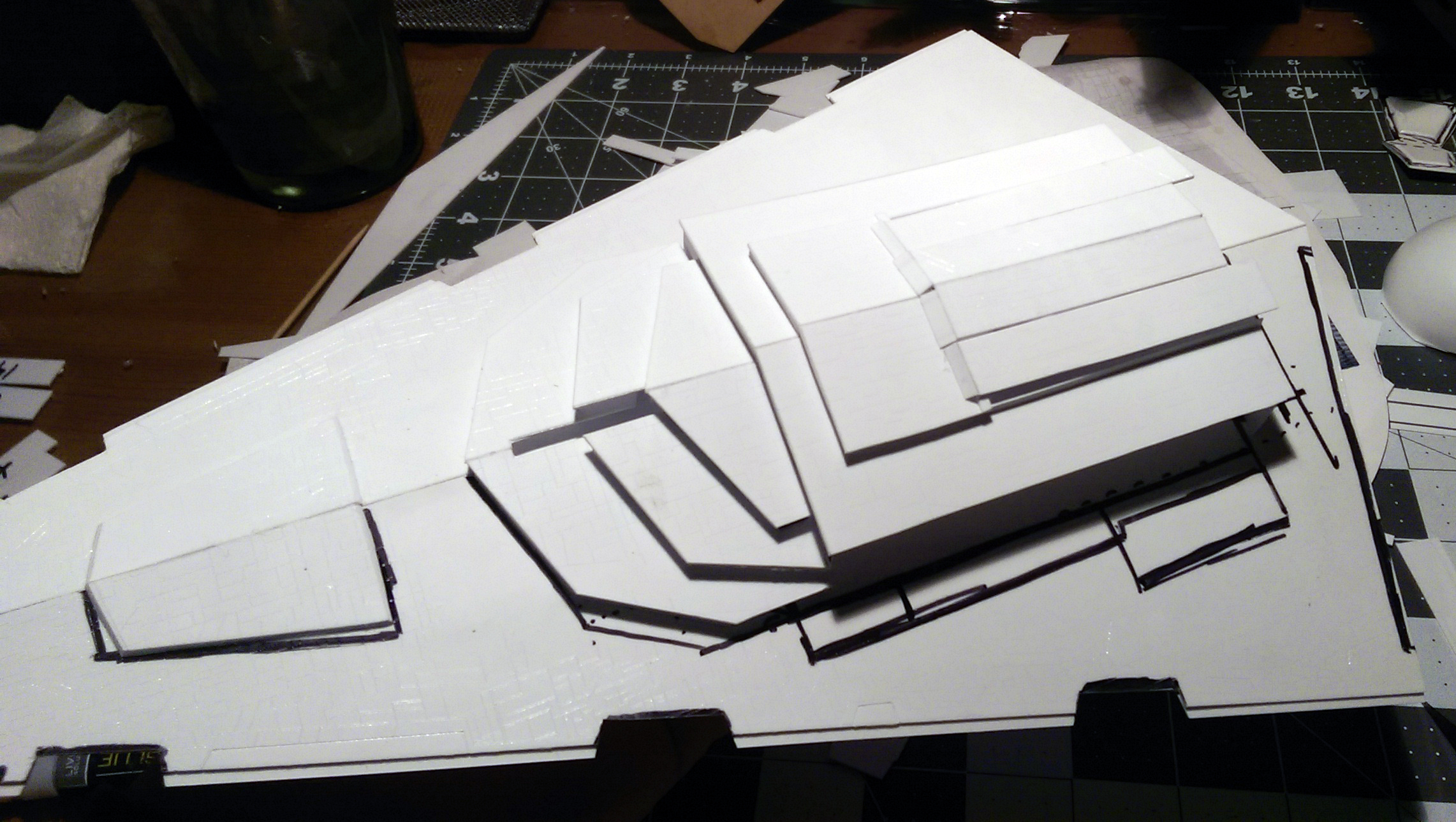
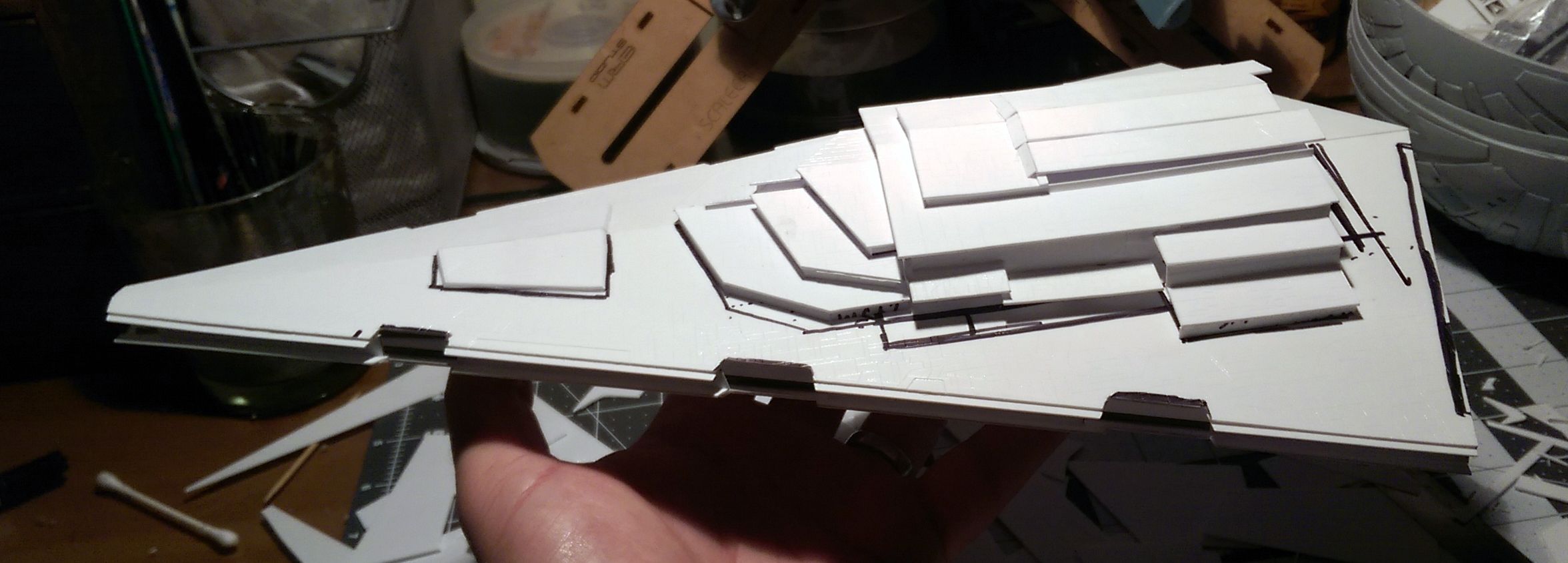
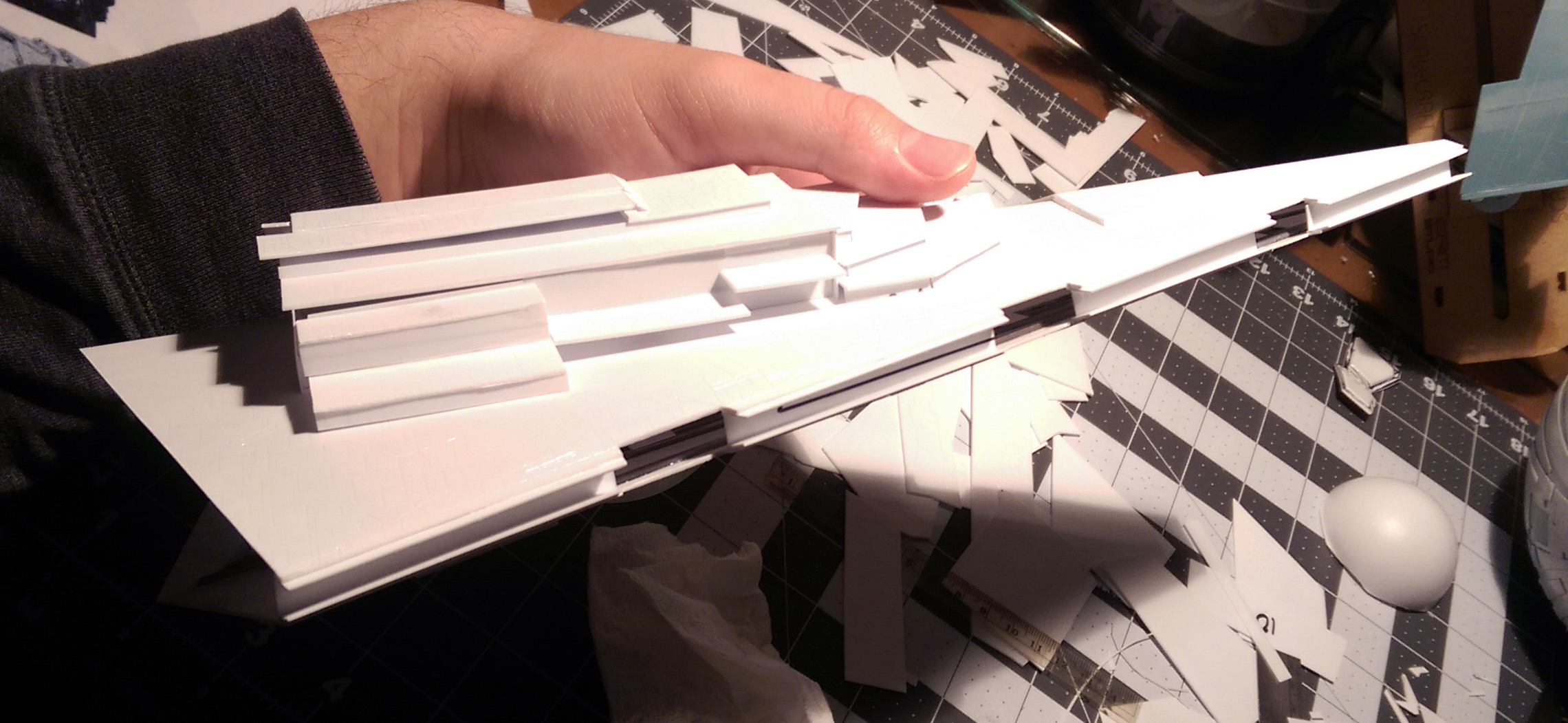
Onto the parts! I printed off the orthographic images in scale with the parts and began trimming and assembling. Many of the super-structure and raised surface panels are similar to standard ISDs so minimal re-cutting/shaping was necessary to fit the build. I started numbering them in order to keep track of where they will be placed when the time comes.


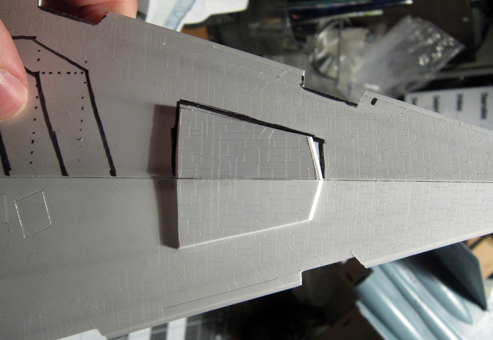
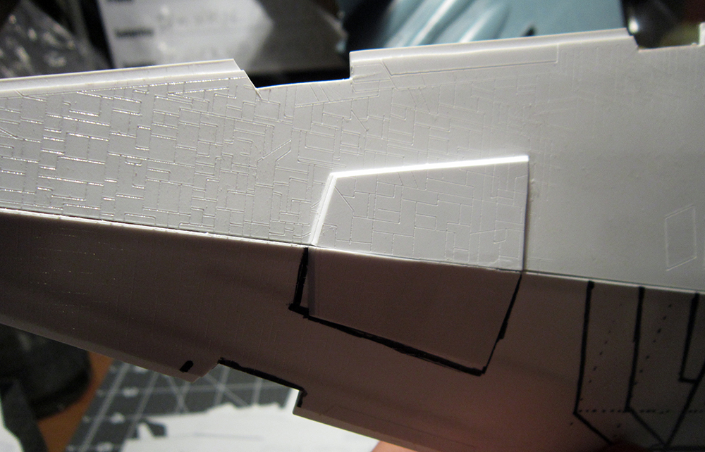
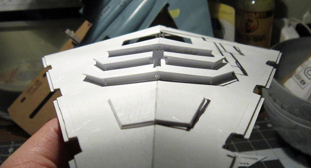
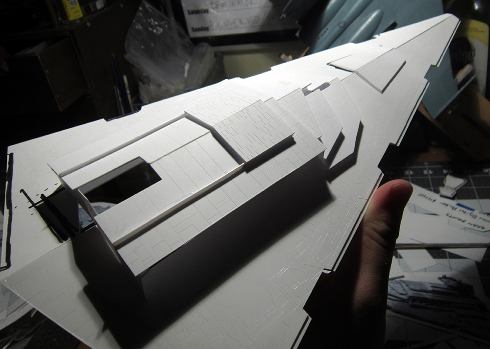
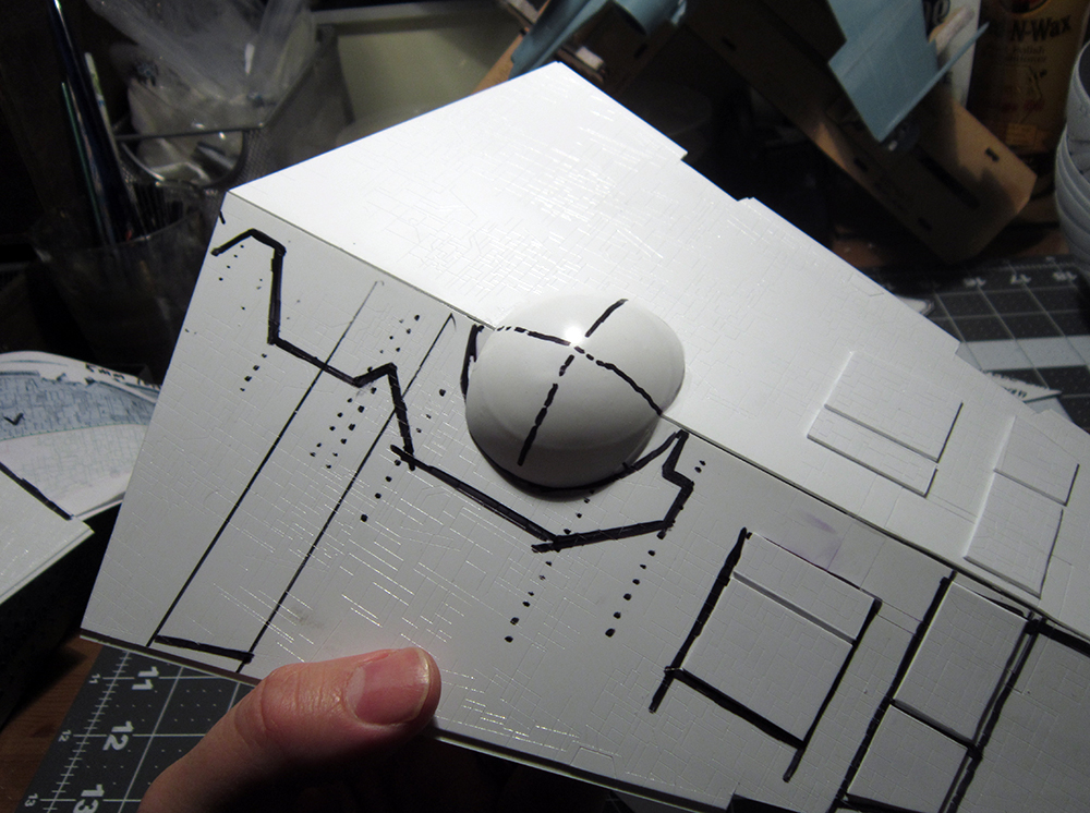
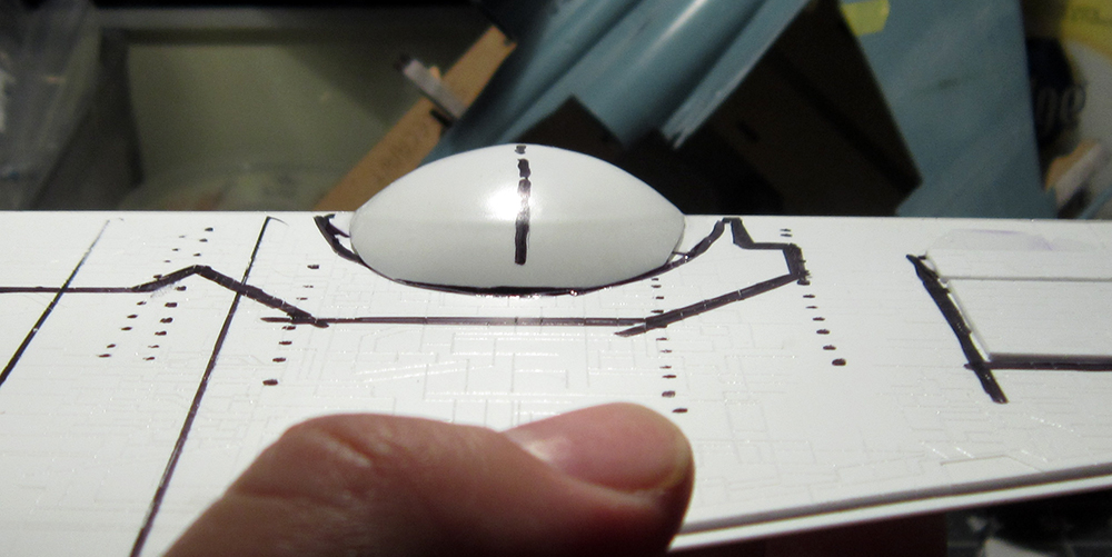
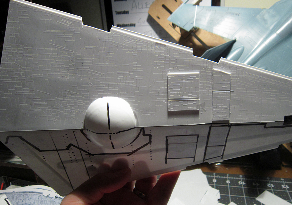
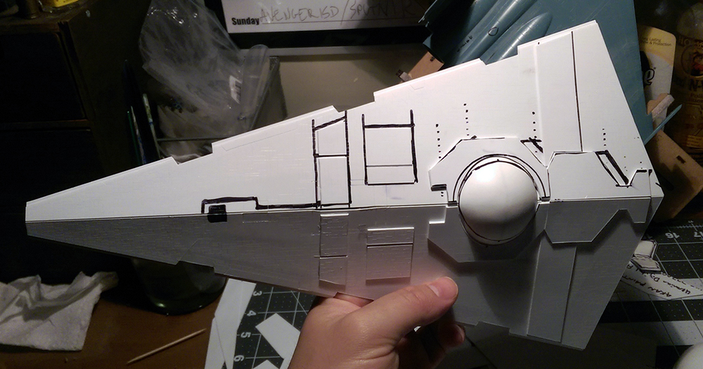
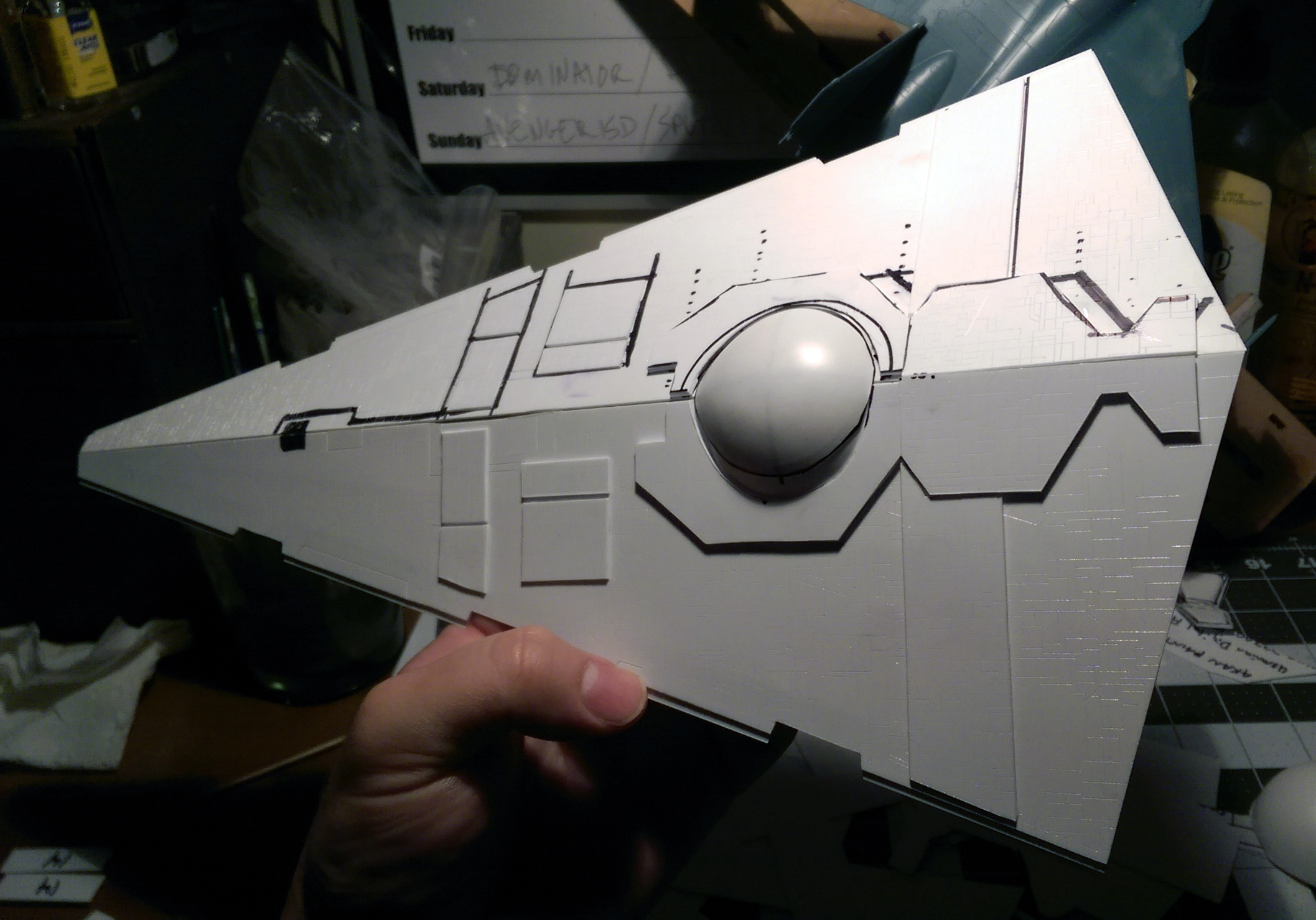
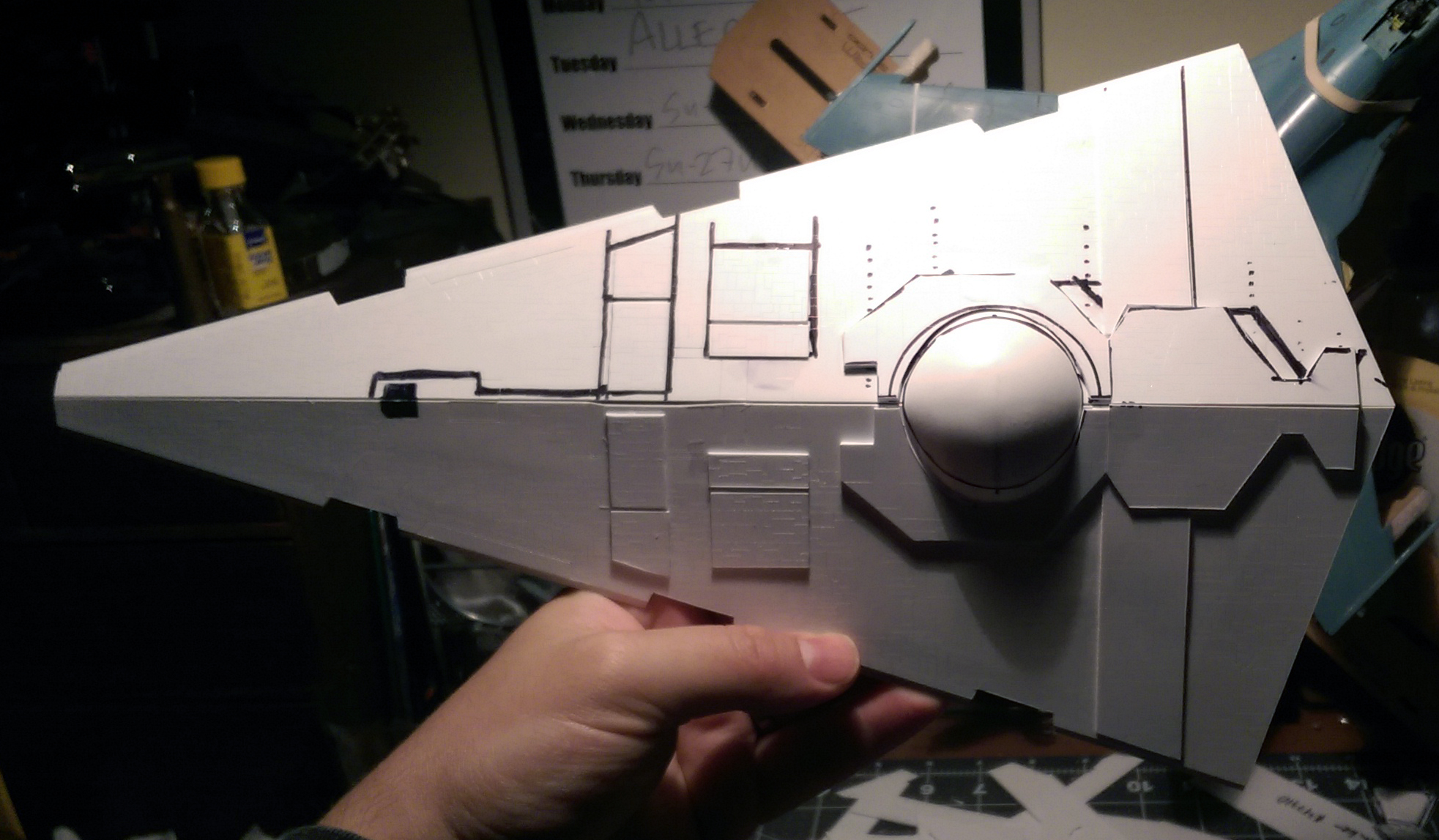
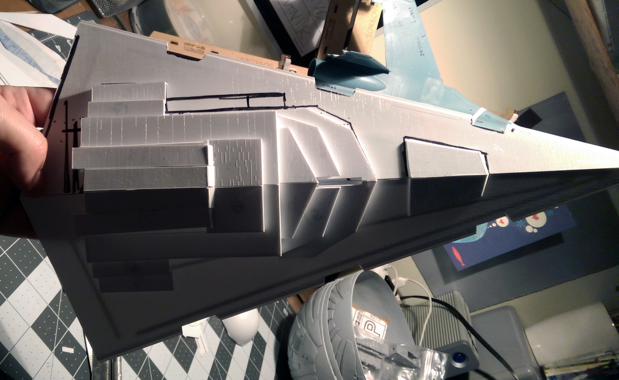
Drawing the outlines of the main shapes on the hull pieces helps keep the final form in mind. And for anyone reading this who hasn’t seen any of my previous Imperial cruiser work, the pieces I use are laser-etched and cut and have a very high level of panel line detail.


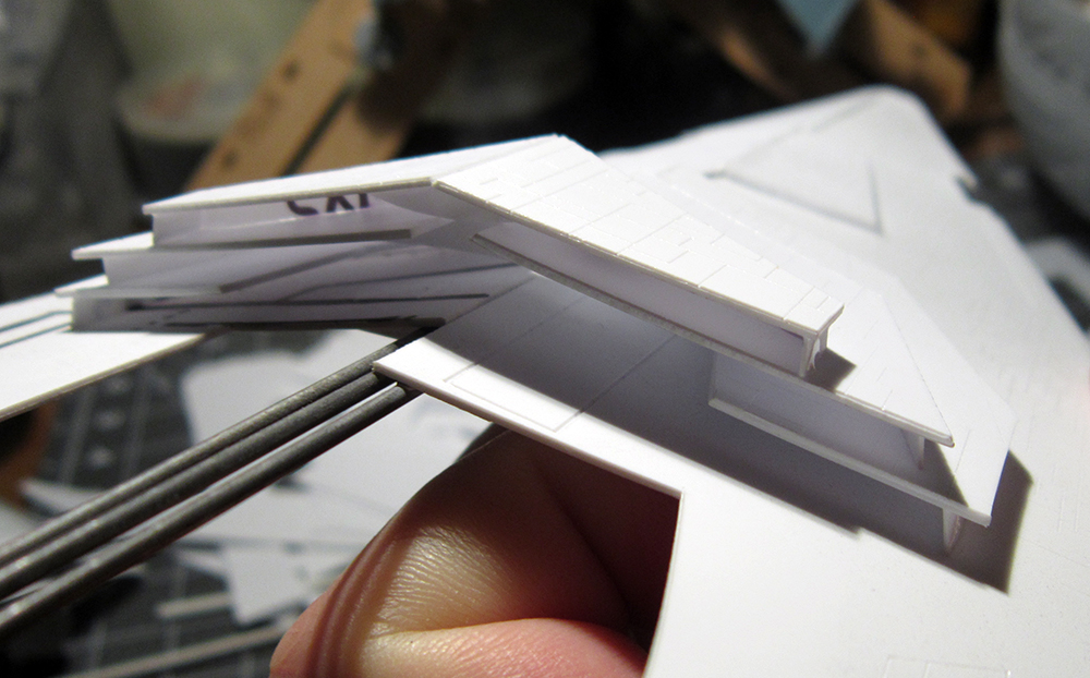
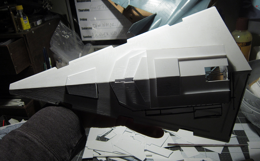
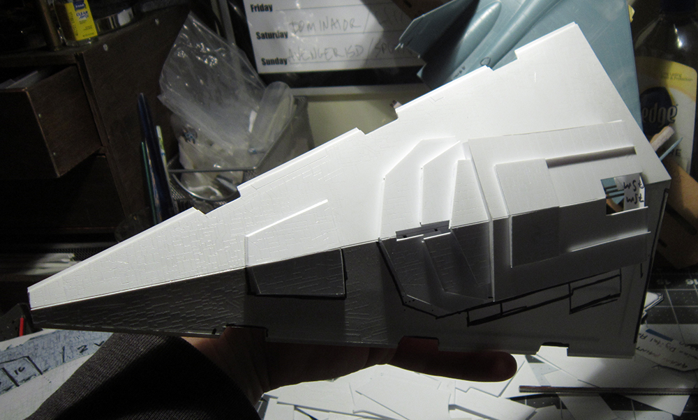
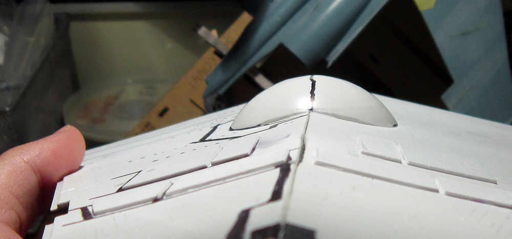
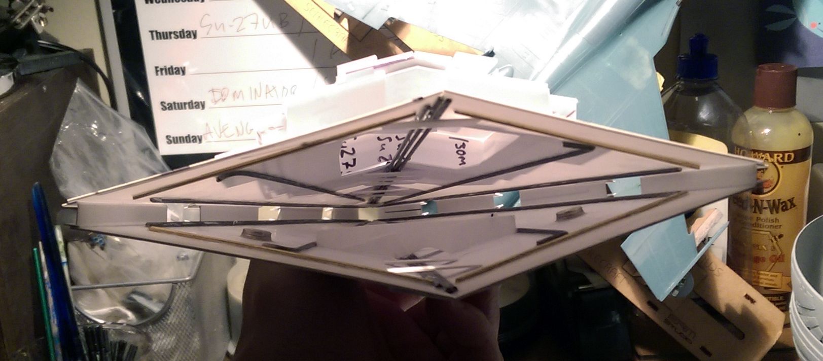
One of the more fundamental parts of an Imperial style build is making sure that the hull lines are nice, sharp and straight. This is accomplished by utilizing steel and brass rods. In this case, I used four per hull plane in order to maintain rigidity. During this stage of the process I also added rare-earth magnets which will serve as mounting points for the eventual support rods. Also, in preparation for the next stage (and equally fundamental step for maintaining a clean form) was constructing a jig to make sure the triangular angles of the hull are consistent.


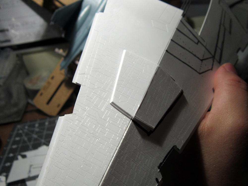
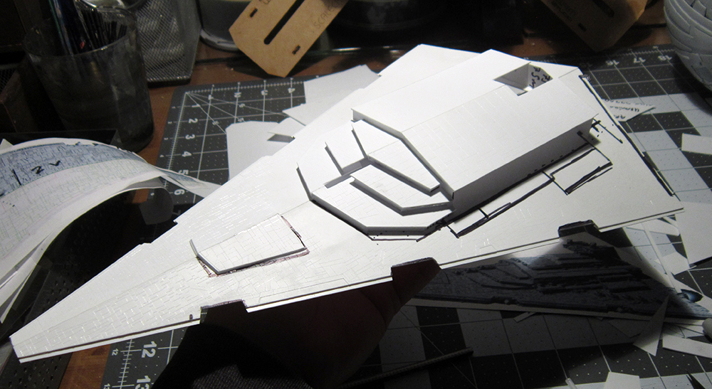
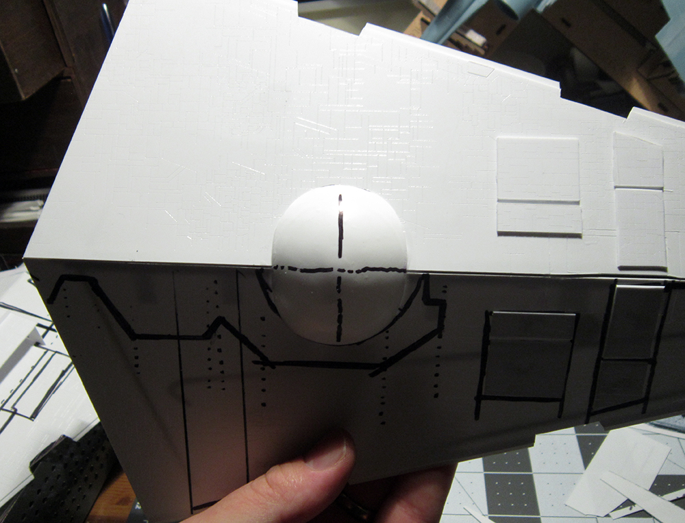
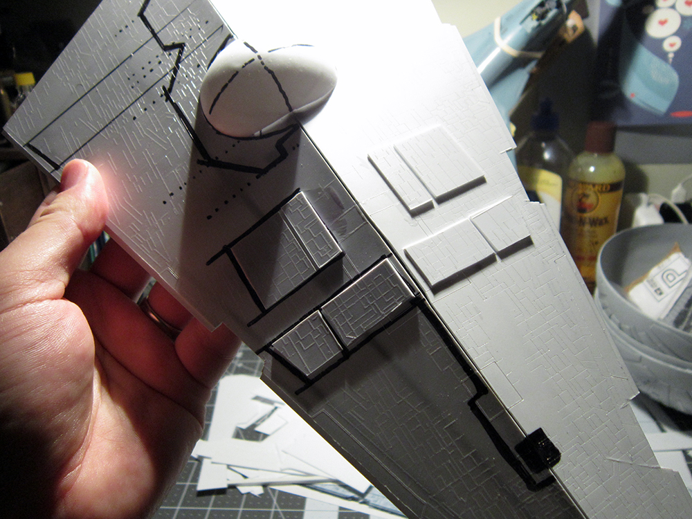
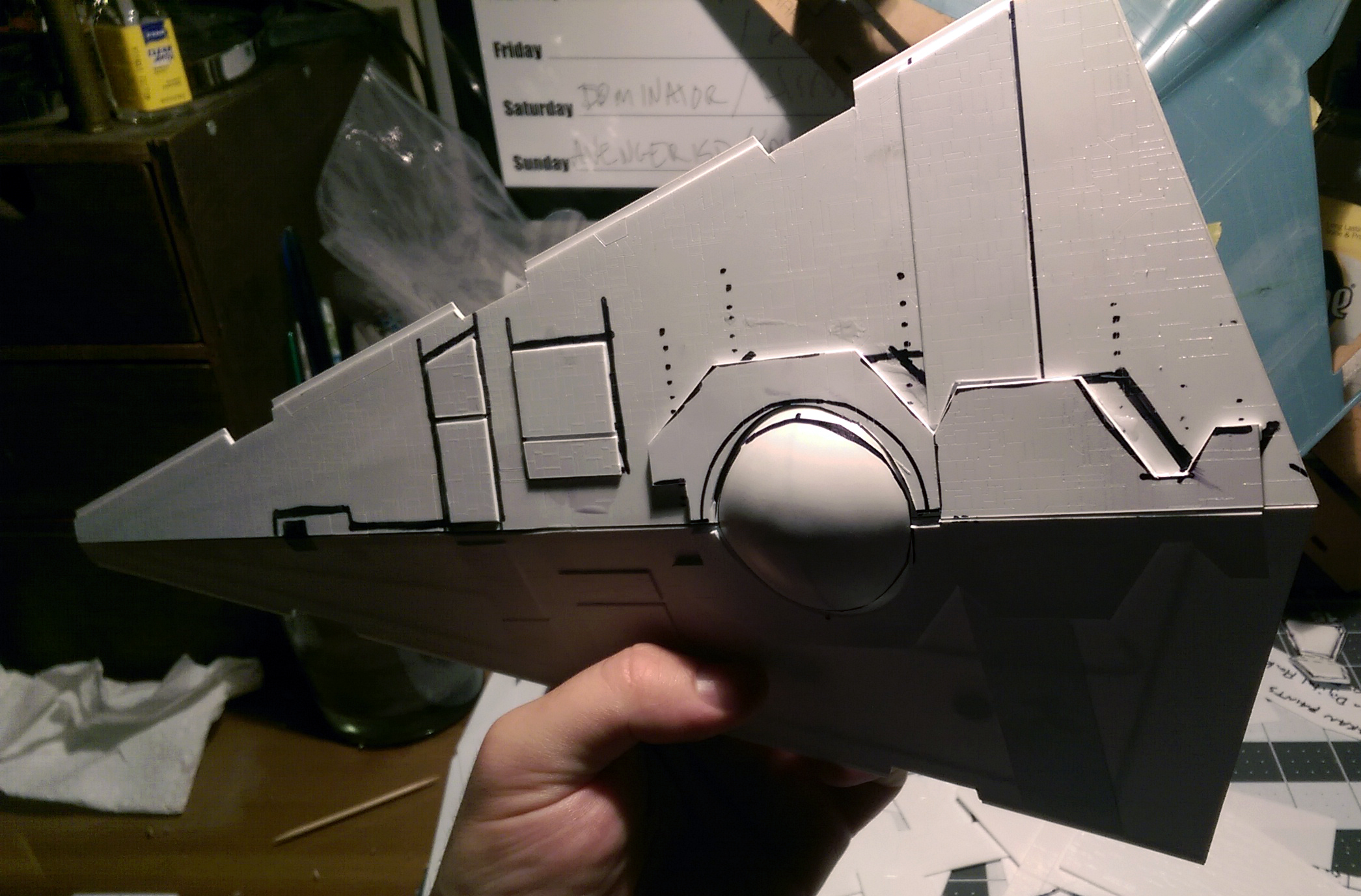
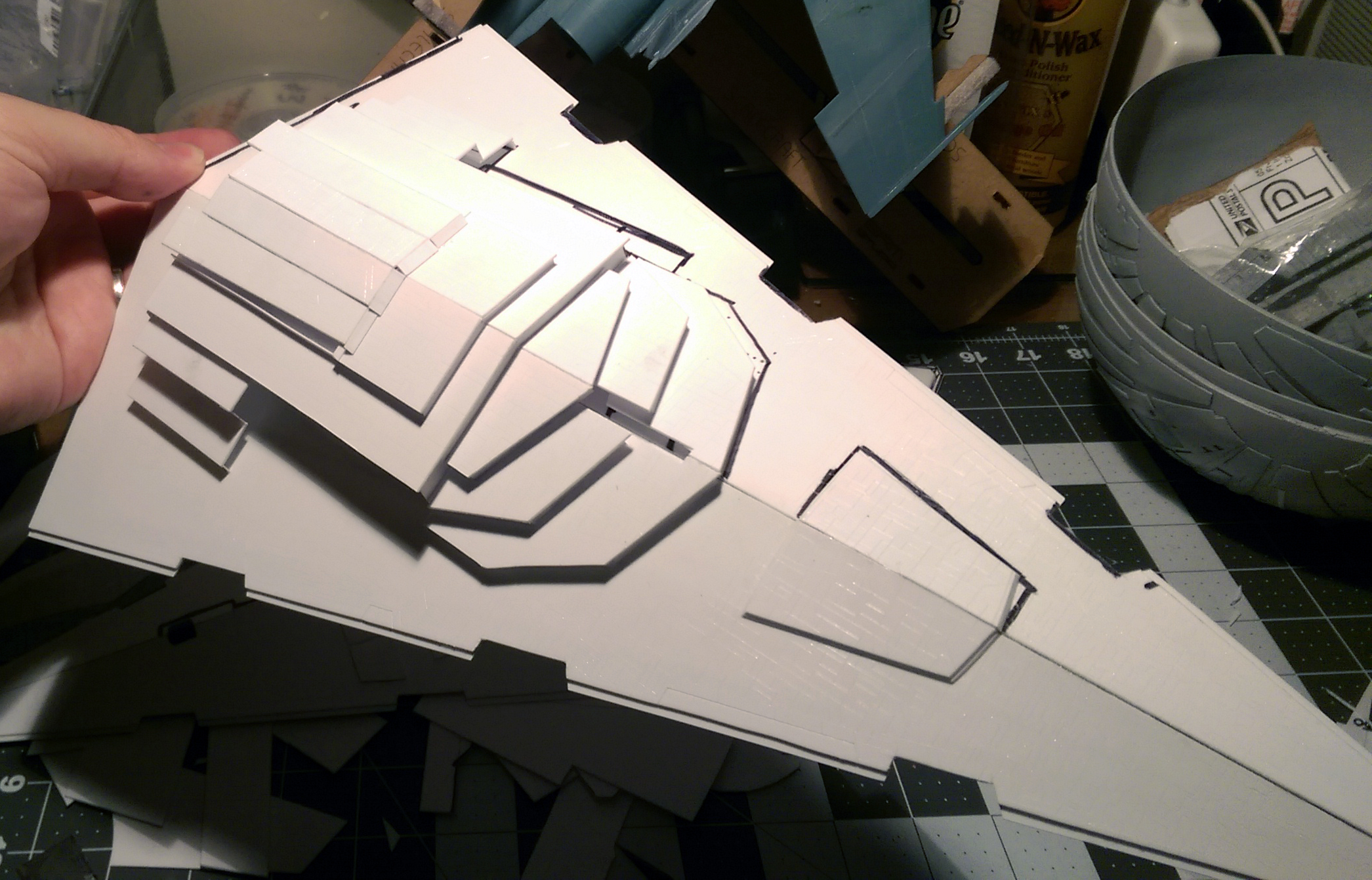
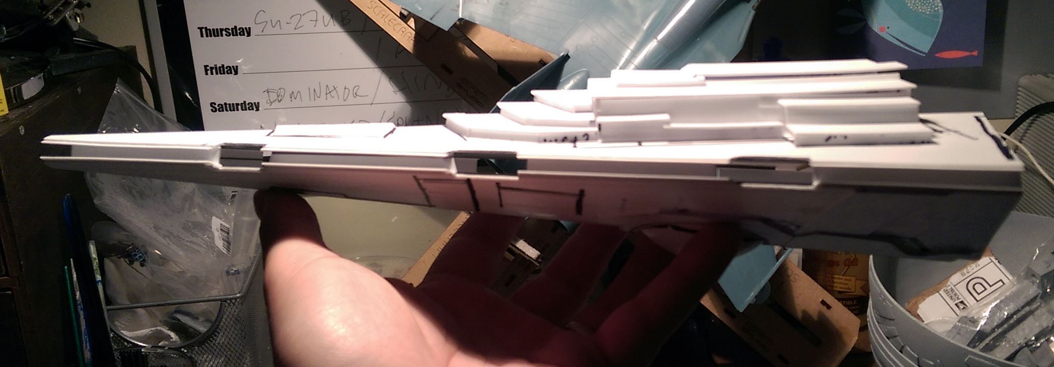
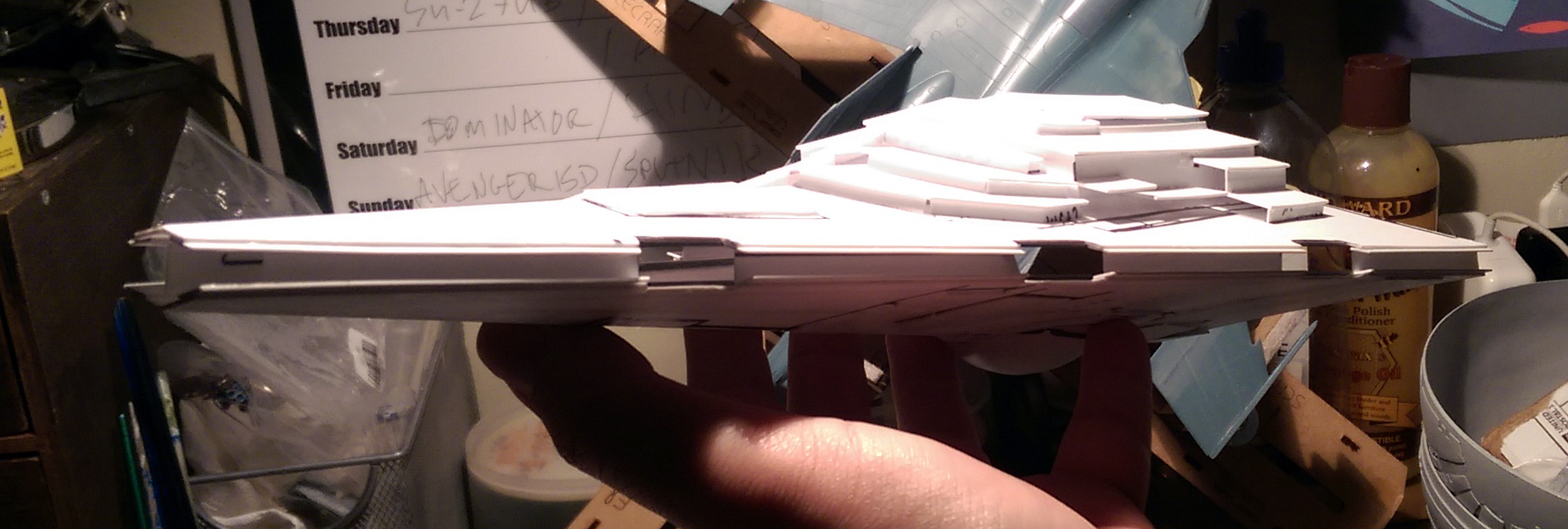
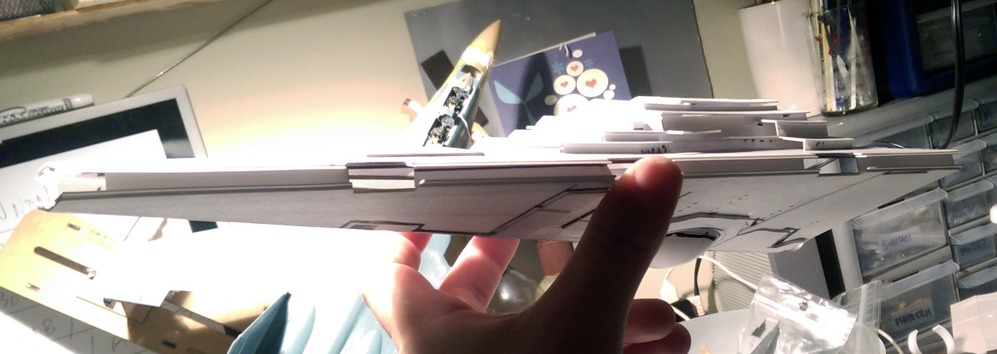
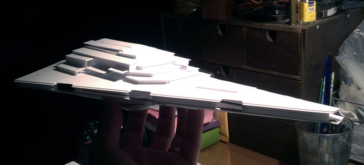
Here are the hulls joined at the proper angles. Now she’s starting to look like a Star Destroyer! In the past I’ve added additional supports as crossbeams, or bulkheads. This time I decided to put strengthening strips across the center line to create a horizontal ribbing. So far it feels more secure than the older method, mostly because there’s more surface area connecting the two hull halves. Last little step in this update was cutting out the insets on the side trench lips. They are arranged differently than the pattern that was laser-etched, but weren’t difficult to cut out. Much of the bare-detail areas where the original cut outs are will be covered up by edge detailing soon.


Onto the parts! I printed off the orthographic images in scale with the parts and began trimming and assembling. Many of the super-structure and raised surface panels are similar to standard ISDs so minimal re-cutting/shaping was necessary to fit the build. I started numbering them in order to keep track of where they will be placed when the time comes.
Drawing the outlines of the main shapes on the hull pieces helps keep the final form in mind. And for anyone reading this who hasn’t seen any of my previous Imperial cruiser work, the pieces I use are laser-etched and cut and have a very high level of panel line detail.
One of the more fundamental parts of an Imperial style build is making sure that the hull lines are nice, sharp and straight. This is accomplished by utilizing steel and brass rods. In this case, I used four per hull plane in order to maintain rigidity. During this stage of the process I also added rare-earth magnets which will serve as mounting points for the eventual support rods. Also, in preparation for the next stage (and equally fundamental step for maintaining a clean form) was constructing a jig to make sure the triangular angles of the hull are consistent.
Here are the hulls joined at the proper angles. Now she’s starting to look like a Star Destroyer! In the past I’ve added additional supports as crossbeams, or bulkheads. This time I decided to put strengthening strips across the center line to create a horizontal ribbing. So far it feels more secure than the older method, mostly because there’s more surface area connecting the two hull halves. Last little step in this update was cutting out the insets on the side trench lips. They are arranged differently than the pattern that was laser-etched, but weren’t difficult to cut out. Much of the bare-detail areas where the original cut outs are will be covered up by edge detailing soon.
")