1/100 U-VII C U-Boat

Scale Model Addict - Model Tips, Guides, Tools & Tech, Tutorials, and Community

Help Support Scale Model Addict:

Tonight's update.
I would like thank those that are viewing this build as it encourages me to do better.

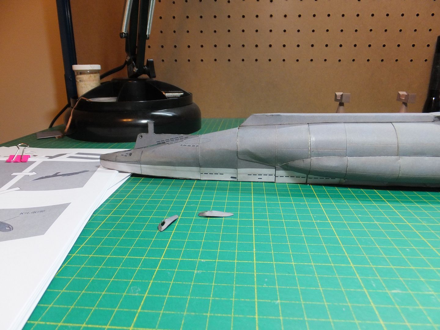
Today have been working on the stern area. the vertical plane was assembled. With the double thickness of card in the core of this piece then the 2 printed pieces on top of that, makes this plane 4 card thick ( 1mm ). This was then installed along with the exit ports for the prop shafts.

Here we see the vertical plane installed and the 2 shaft ports ready to be placed.

Stern1_zpsbf49bfd1.jpg


Another view of the vertical plane and the shaft ports installed.

Stern2_zps030e3708.jpg


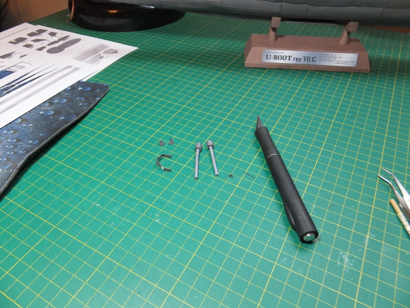
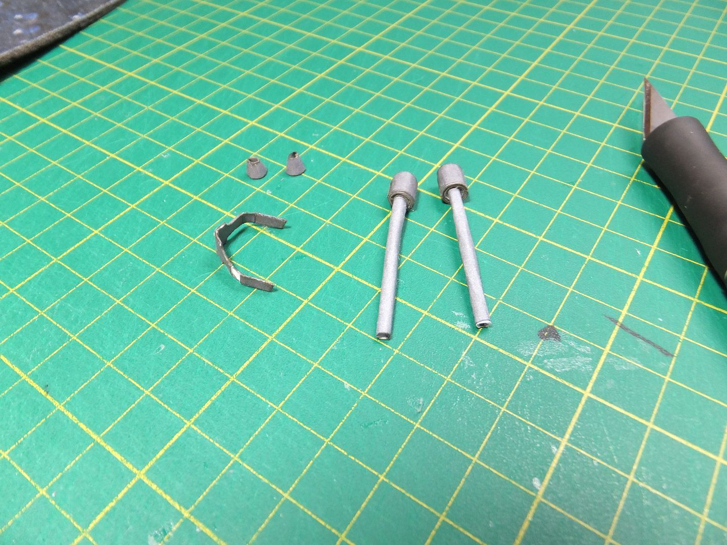
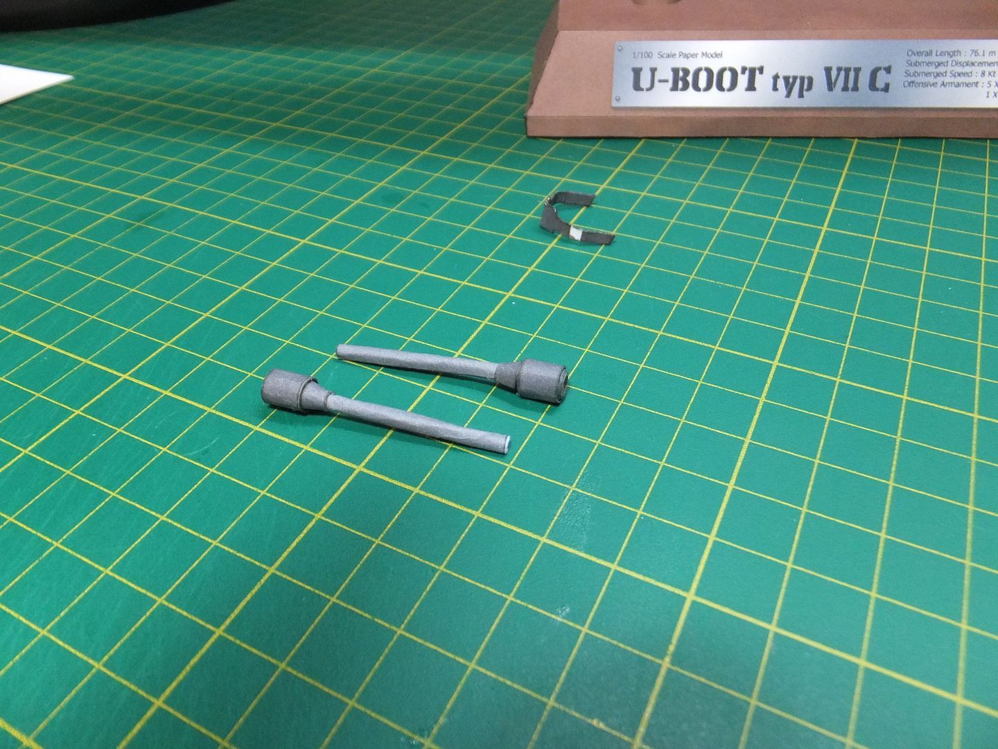
Next up, the prop shafts had to be rolled and glued. Then the outer shaft bearings were rolled on to the ends of the shafts. As well the cones were constructed for part of the bearing assembly and the support brace was folded and glued.

Stern3_zps2d5ec1f0.jpg


A closer view of these parts.

Stern4_zpsaa451676.jpg


The shafts fully assembled.

Stern5_zps813c0ce0.jpg


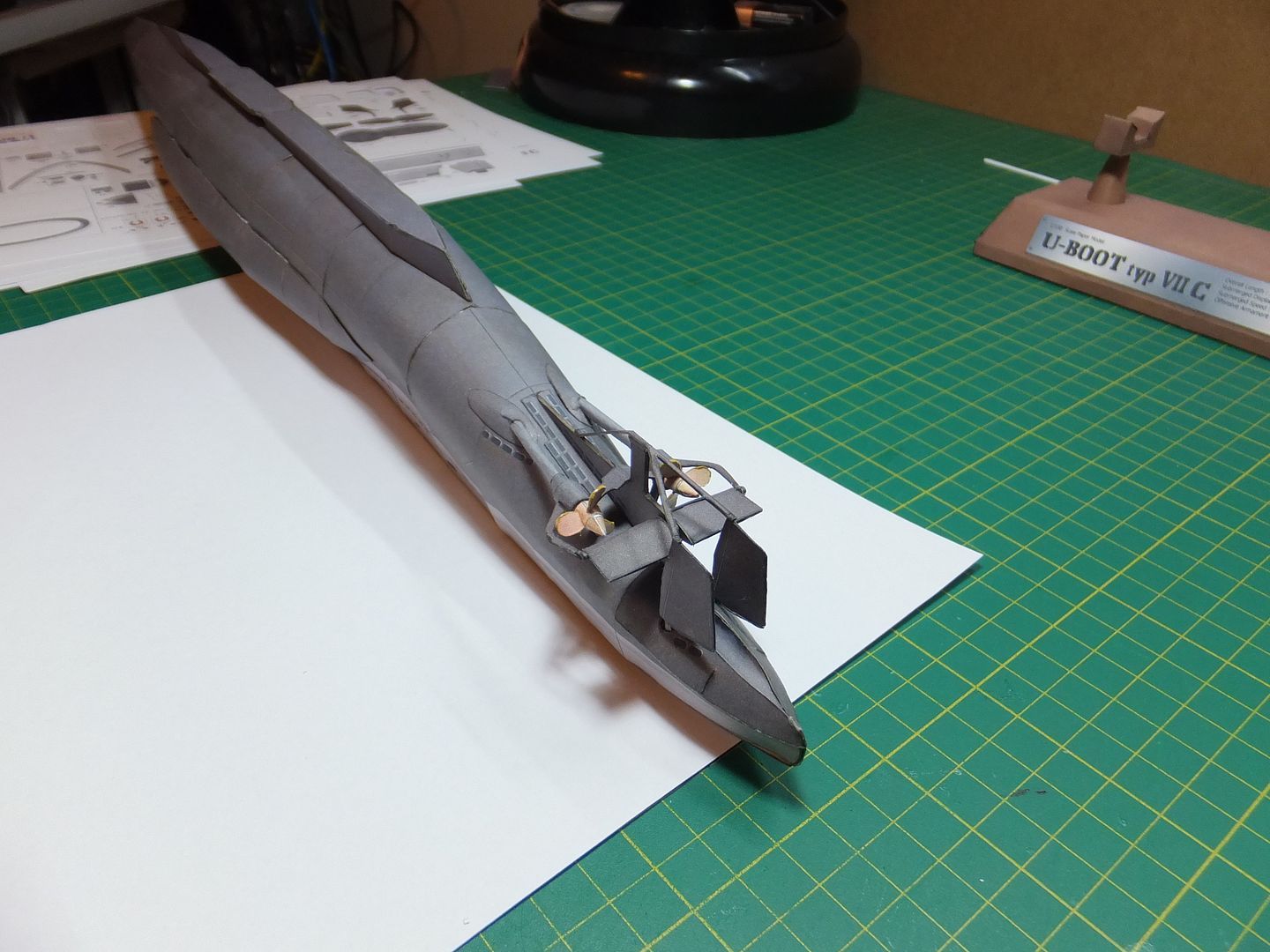
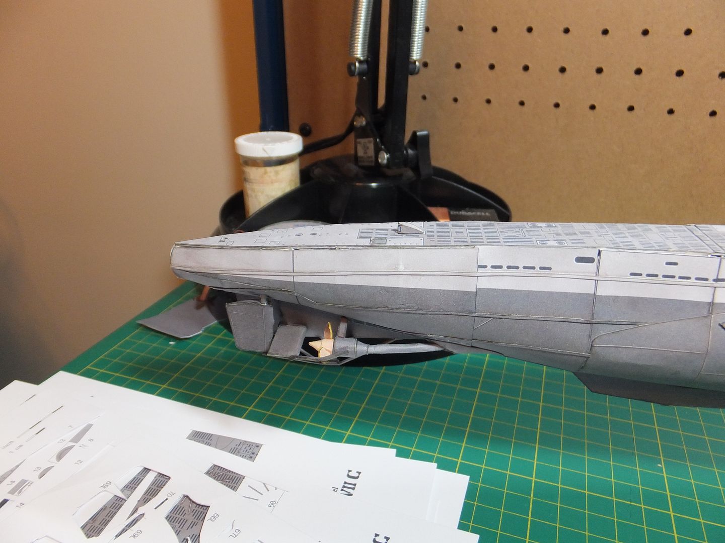
All those pieces were the installed on to the model. Here is a view of this stage.

Stern6_zps1e8efbee.jpg


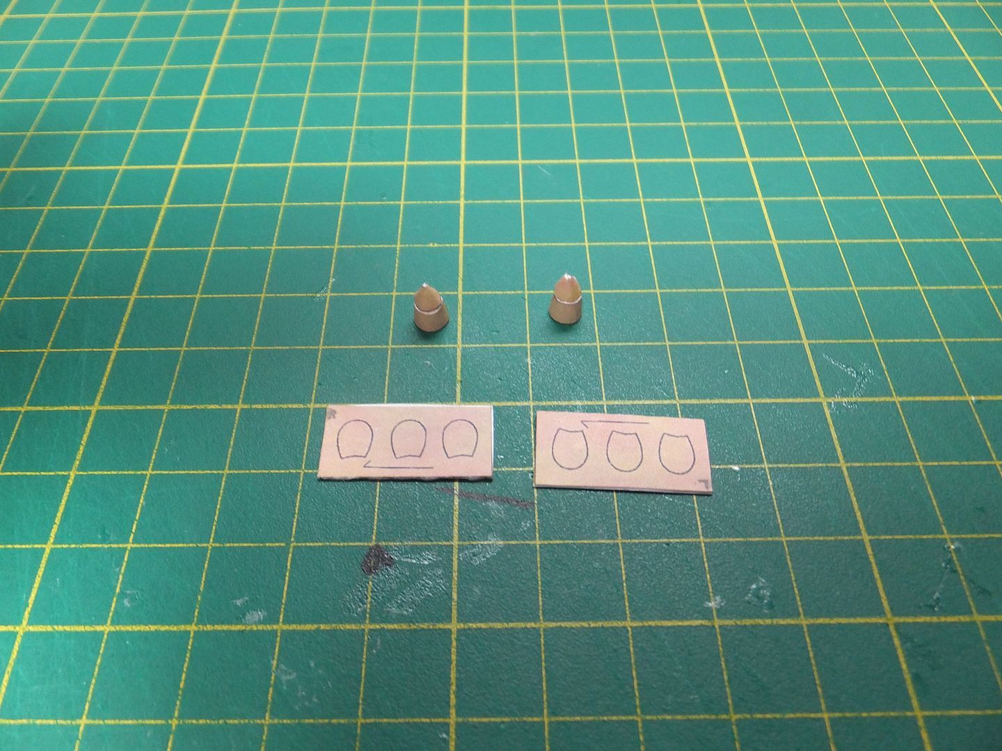
Tonight have been working on the props themselves. the hubs and cones have been rolled and assembled. The blades still have to be cut out and shaped, before they can be applied to the hubs.

Stern7_zps7b7050d3.jpg


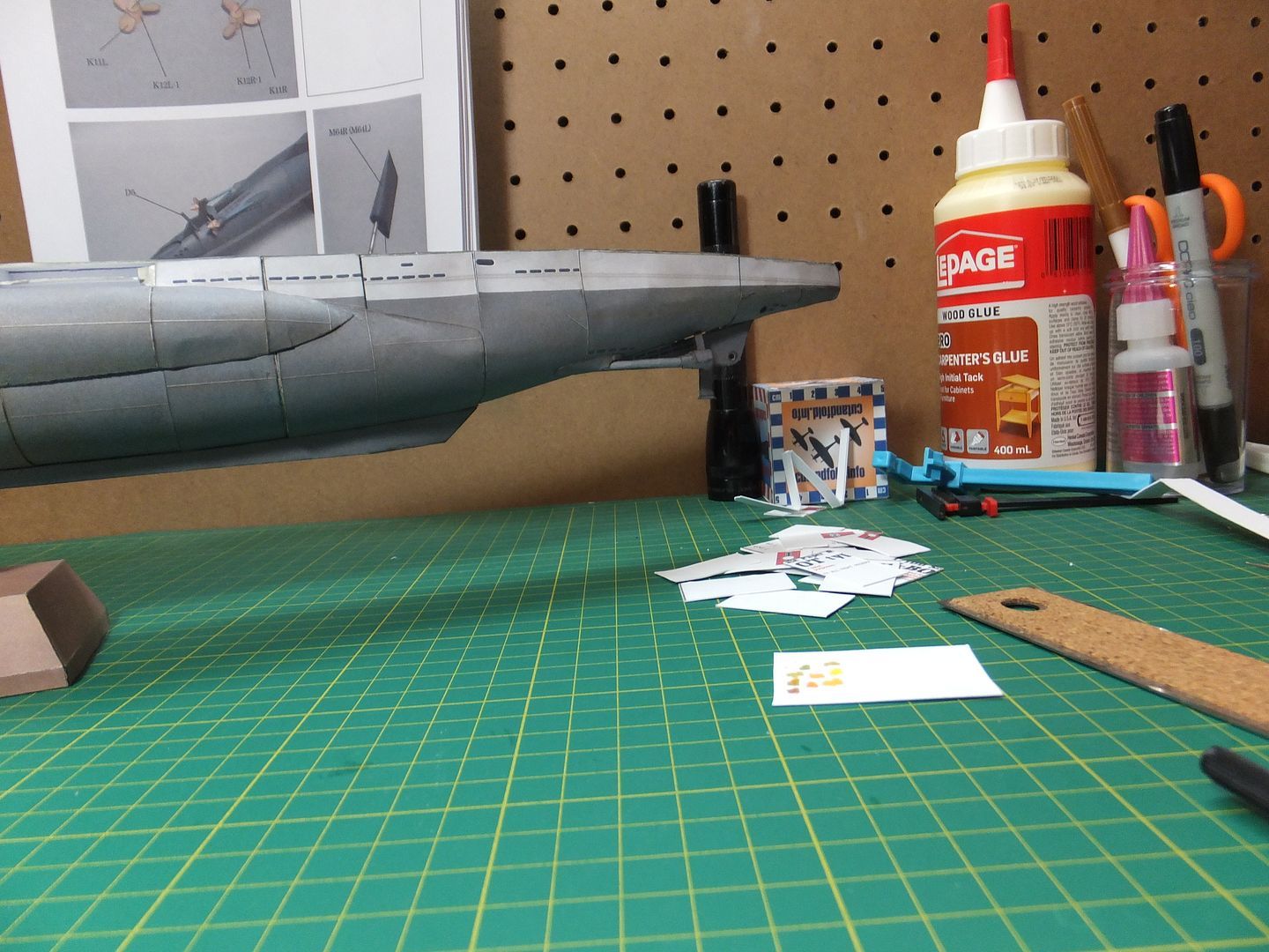
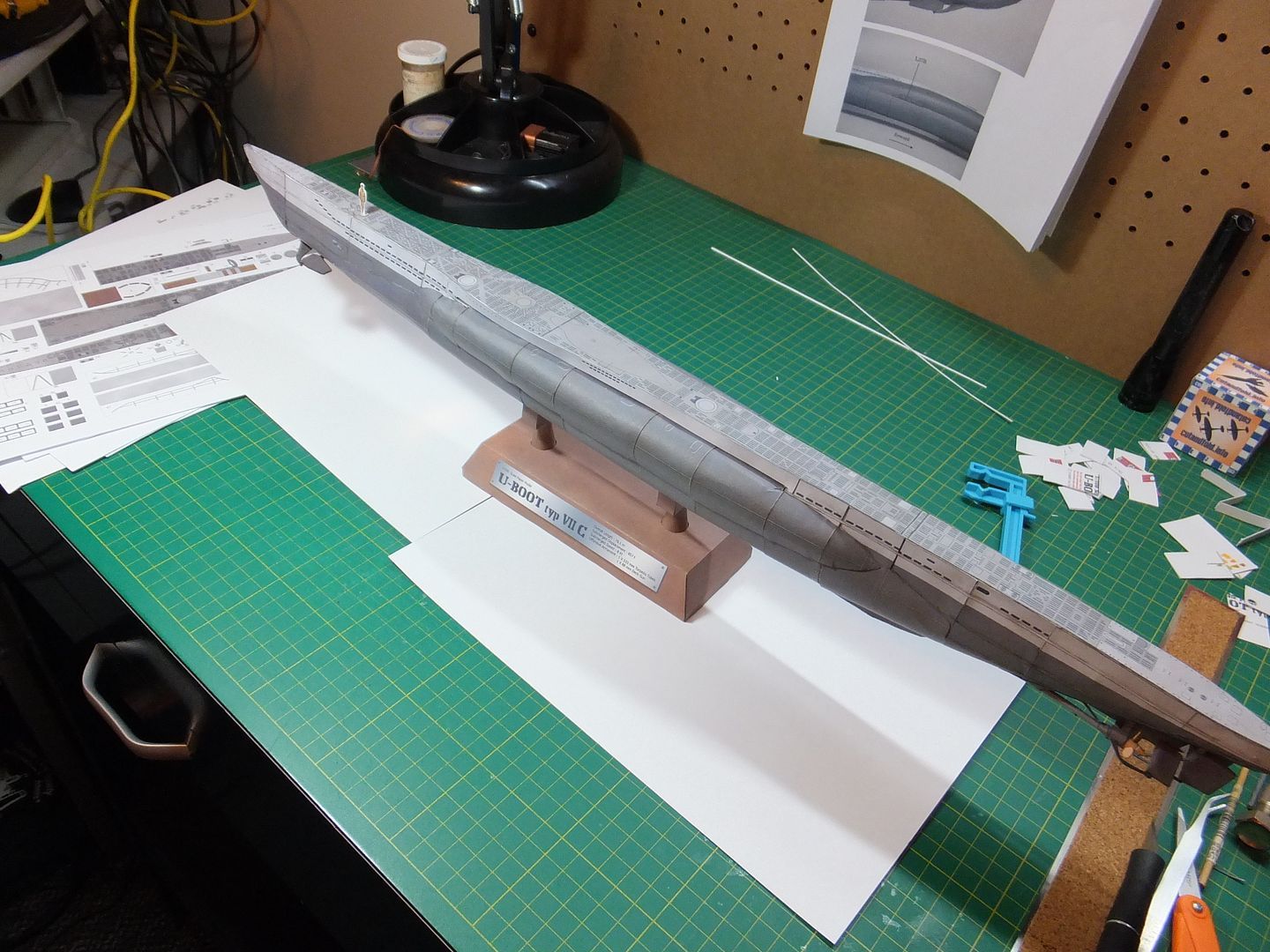
This is just a view of the stern as she looks tonight.

Stern8_zpsc0bf7eeb.jpg


Tomorrow hope to complete the props and have them attached. Then to see what else can be achieved.
Will update soon and questions and comments are always welcome.

Jim
 
Hello, short update.
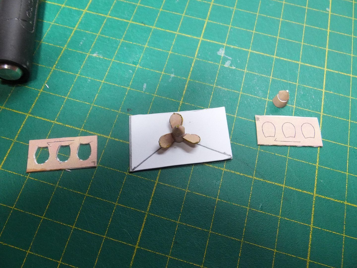
Tonight I am working on the props. Made a simple jig to help with the alignment of the blades, and gave the blades a slight twist before attaching. These are counter rotating, so the second one will have the opposite pitch.

One down one to go.

Props1_zpsfc2fe0e9.jpg


Thank you for watching.

Jim
 
Thank you Grendels.
Those are the first ones I've ever made. When dry fitting could not get the blades to line up by winging it. Had to make the jig. It was fairly simple after that and looking at some real props helped with the shape.

Jim
 
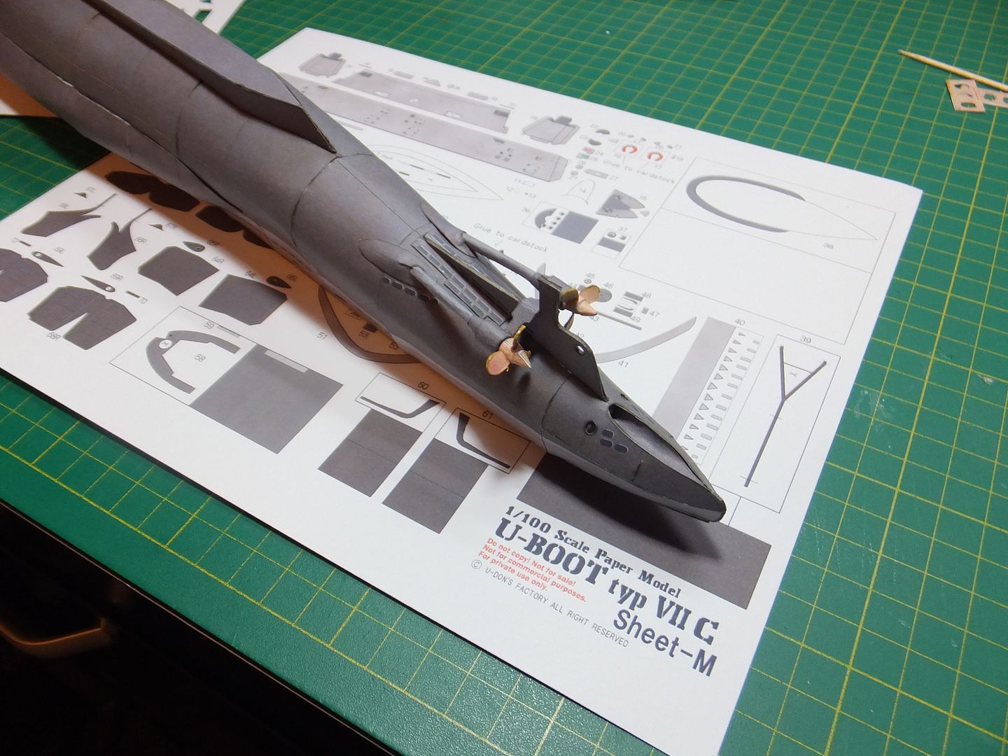
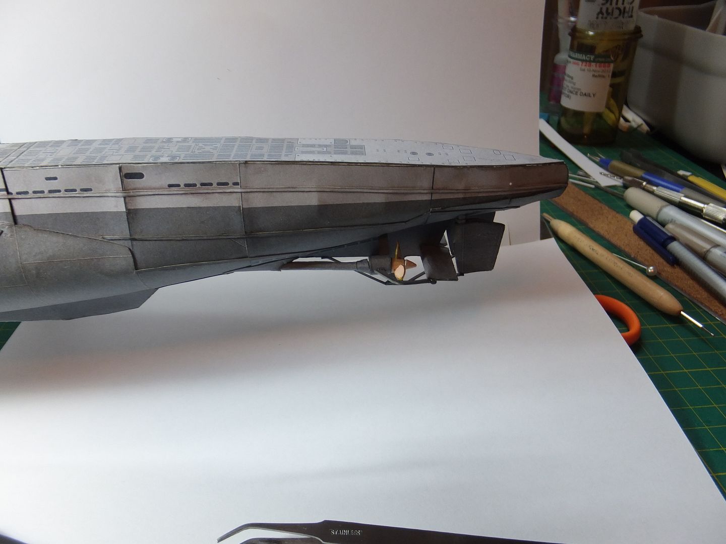
Well finished the props and have them installed. It feels more like a ship to have the screws on.

Props3_zps2192a93e.jpg


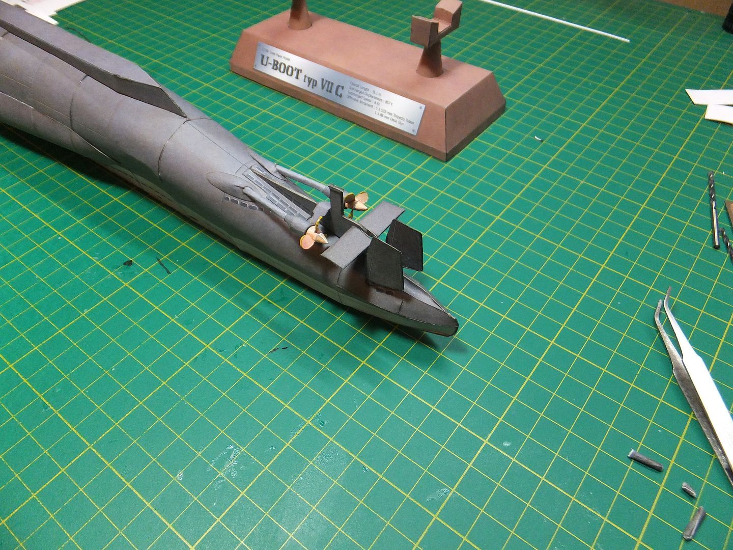
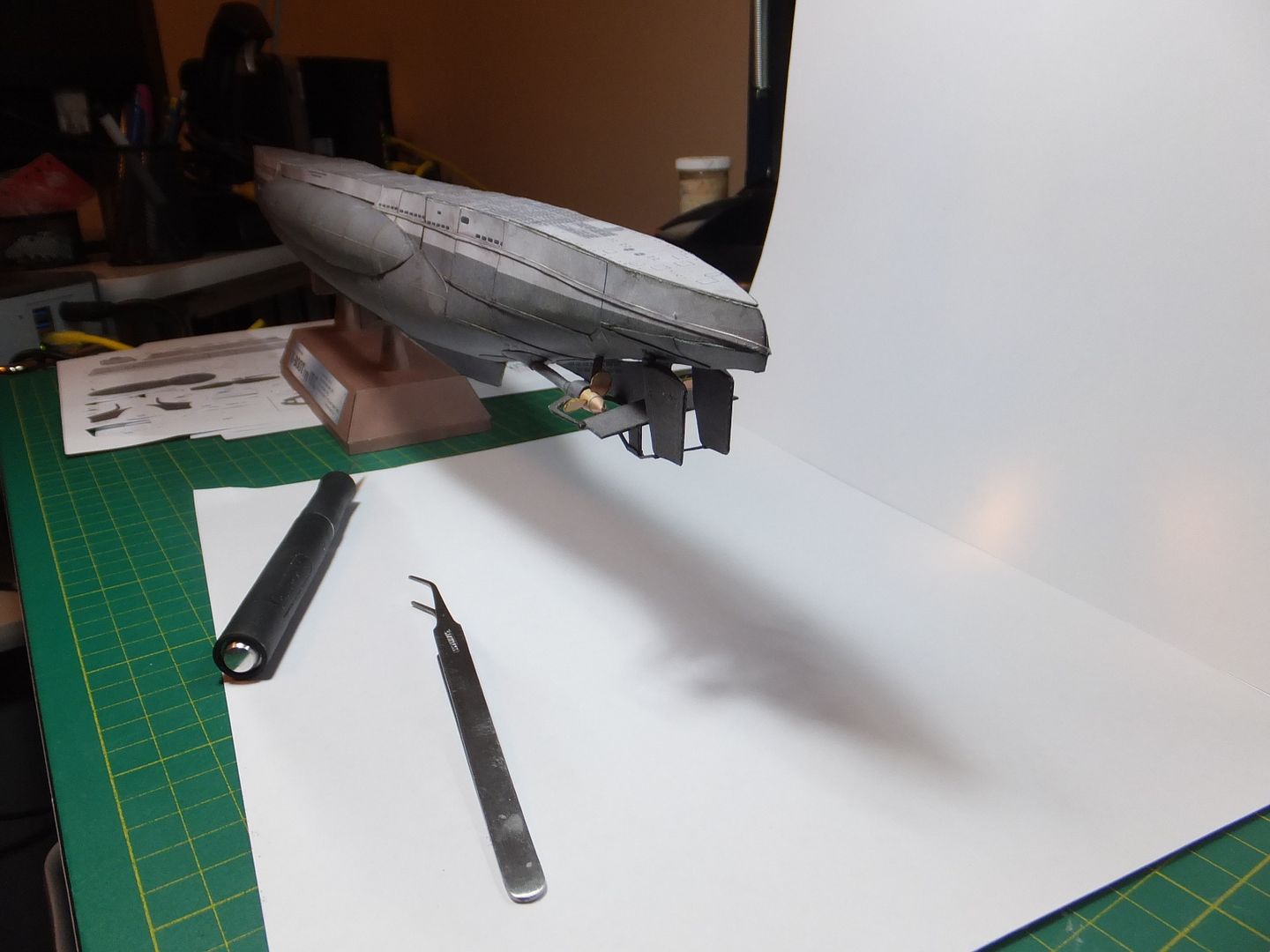
The stern dive planes have been constructed and installed.

DivePlane1_zps12b76a0c.jpg


Finally the upper centre hull skin has been installed. No more visible superstructure.
I thought there was going to be problems with these after the problems with the saddle tanks, but no.
They went on quite easily, no mods.

DivePlane2_zps72395eeb.jpg


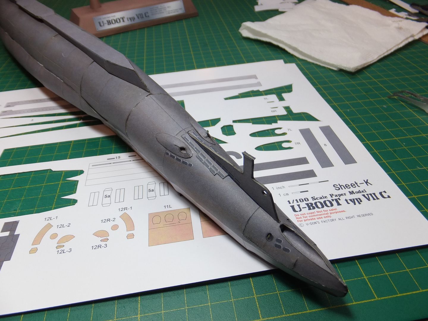
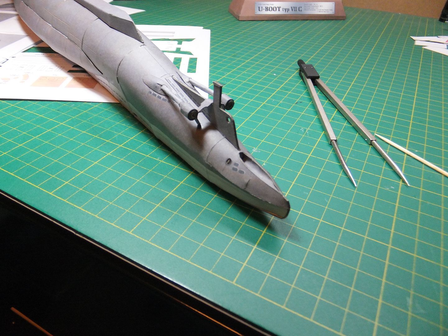
Some detail was added to the bow area.

Bow1_zpsa347dd8d.jpg


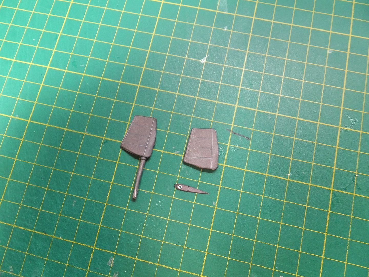
Tonight started working on the rudders. One is complete.

Rudder1_zps907abd6e.jpg


That's it for tonight. Lets see what trouble I can get into with these rudders.

Jim
 
Hello everyone. A short update.
I was able to finish the construction of the rudders this afternoon. They were then installed into the stern and trued up.

Rudder2_zps51a459f0.jpg


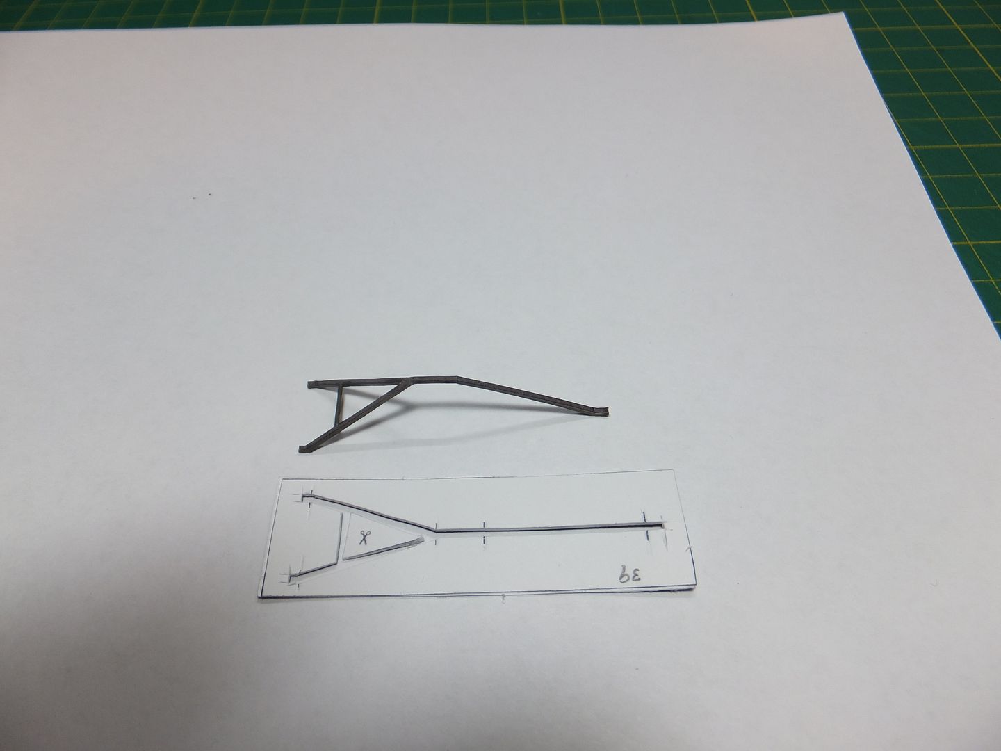
This afternoon laminated the card pieces for the support structure for the rudders and dive planes and let then dry under pressure.
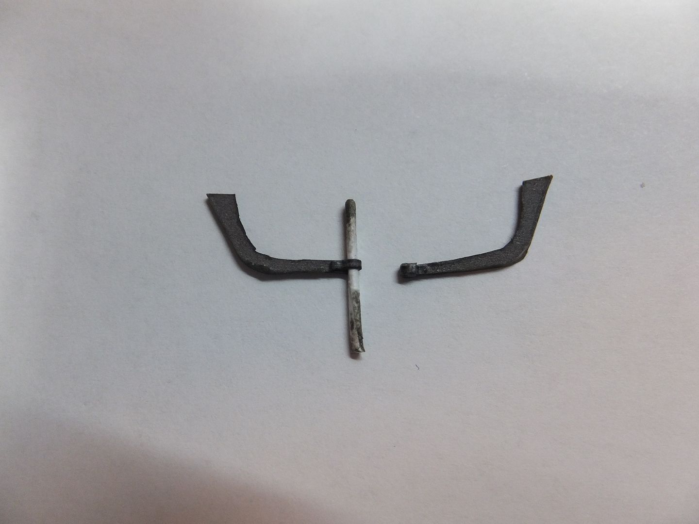
This evening I cut out the outer supports for the dive planes. These are 3 card layers thick except for about 1/4" at the end where they attach to the dive plane. There is no pivot axle on the outside of these dive planes and for this length of card is too difficult to roll without it delaminating. ( Tried it :( ) So instead took a small piece of printer papper and rolled an axle of appropriate diameter. Placed this in position on the brace and wrapped that piece of card over it and gluing in position. Then when dry cut the axle flush and colour it.
The result gives me the look of a proper pivot bearing attachment.

The right one is complete.

DivePlane3_zps79d4396e.jpg


Tomorrow will have these installed and the lower support braces for the rudders cut out.
Comments and questions are always welcome.

Jim
 
Hi Cave Dweller.
This is constructed of 8 1/2" x 11", 110 lb paper card, that is printed through my printer.
It just takes mostly a sharp blade and a steady hand, as well as a vivid imagination. ;D

Jim
 
Tonight's update.
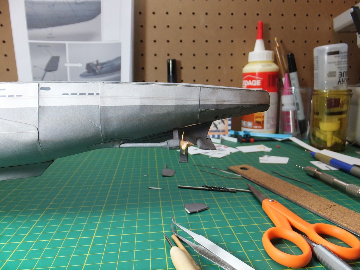
The Pivot supports for the rear dive planes were completed and installed around the props to the dive planes.
The next thing was to cut out the support frame for the rudders and shape and colour the edges.

Rudder3_zpsdde7a3b0.jpg


Here the braces for the dive planes and the rudders are installed.

Rudder4_zpsb0c2f7b0.jpg


After these dried, then on to install some hull plate strap detail to the rear of the hull, as was done to the bow earlier.

Rudder5_zpsabdb11c5.jpg


Just another view.

Rudder6_zps8553176e.jpg


Tomorrow we will move on to the forward dive planes.

I've been heavily documenting this build, trying to show the stages in producing a model of this genre. I hope you are enjoying the journey.

Jim
 
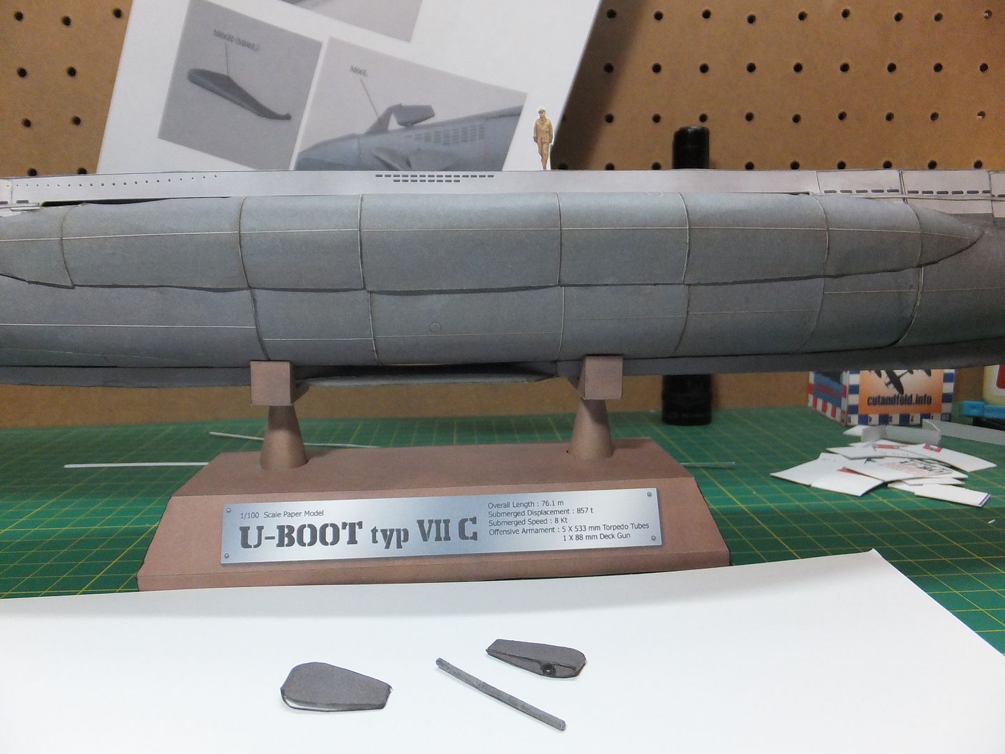
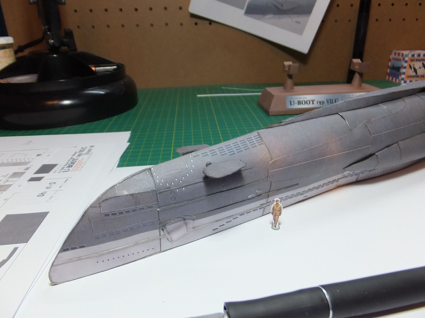
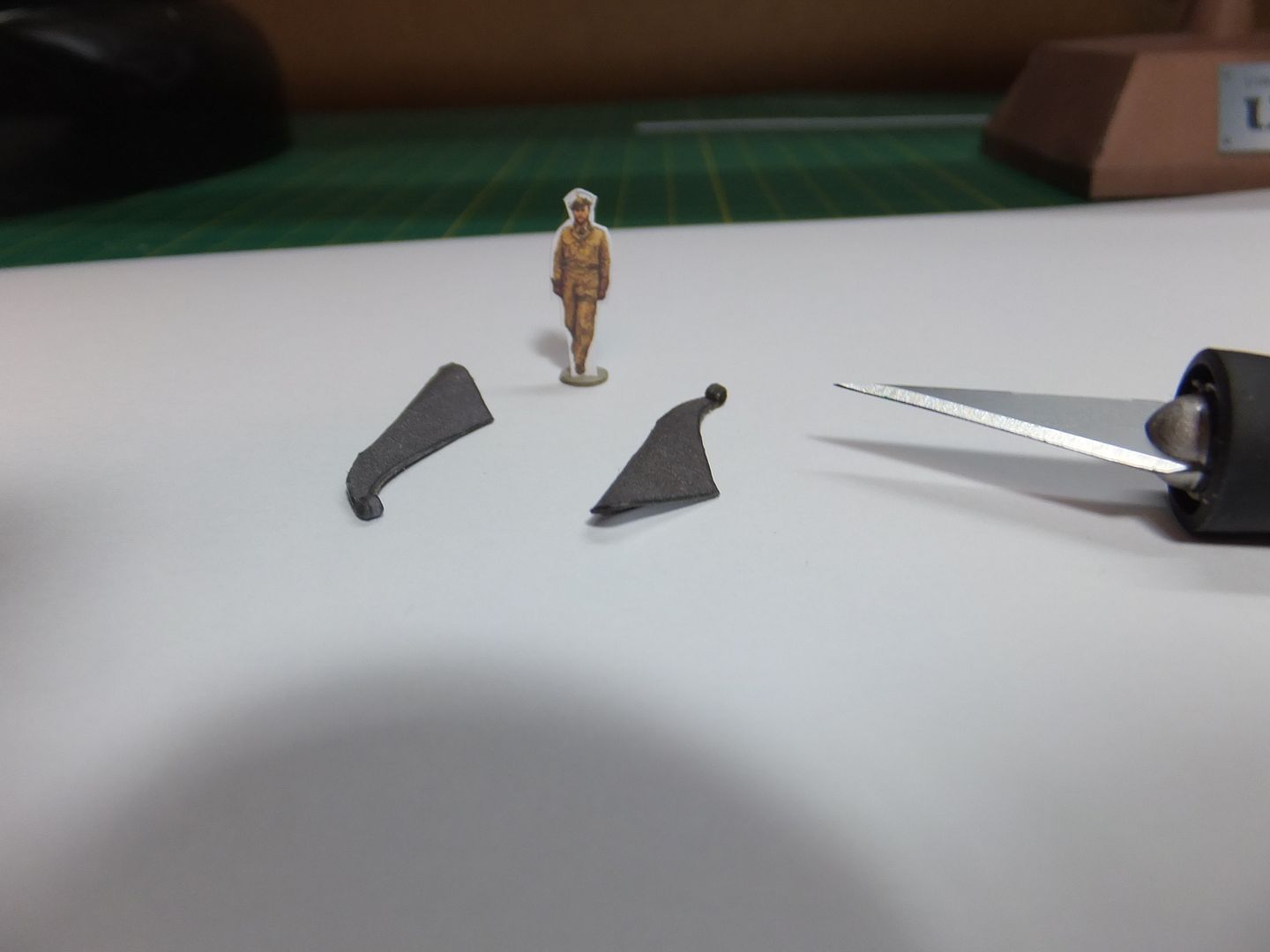
Have been working on the forward dive planes construction and drilled the mounting position for the planes at the bow.

ForwardDivePlanes_zps61c168a7.jpg


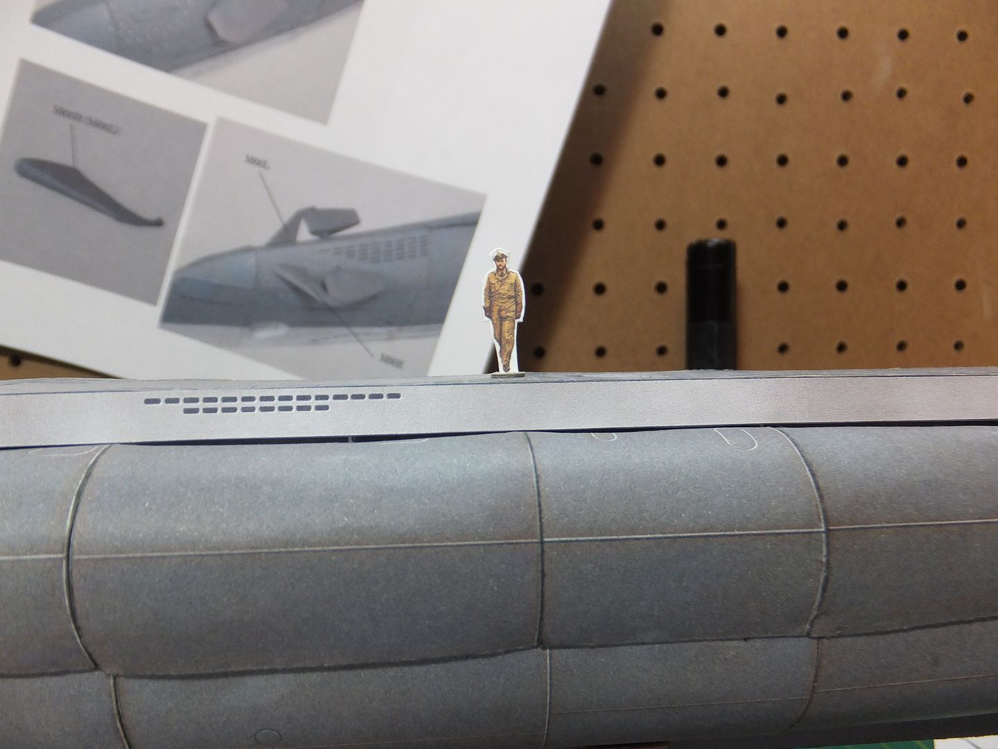
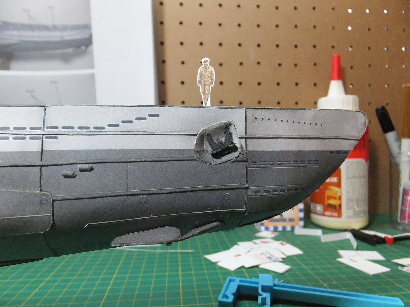
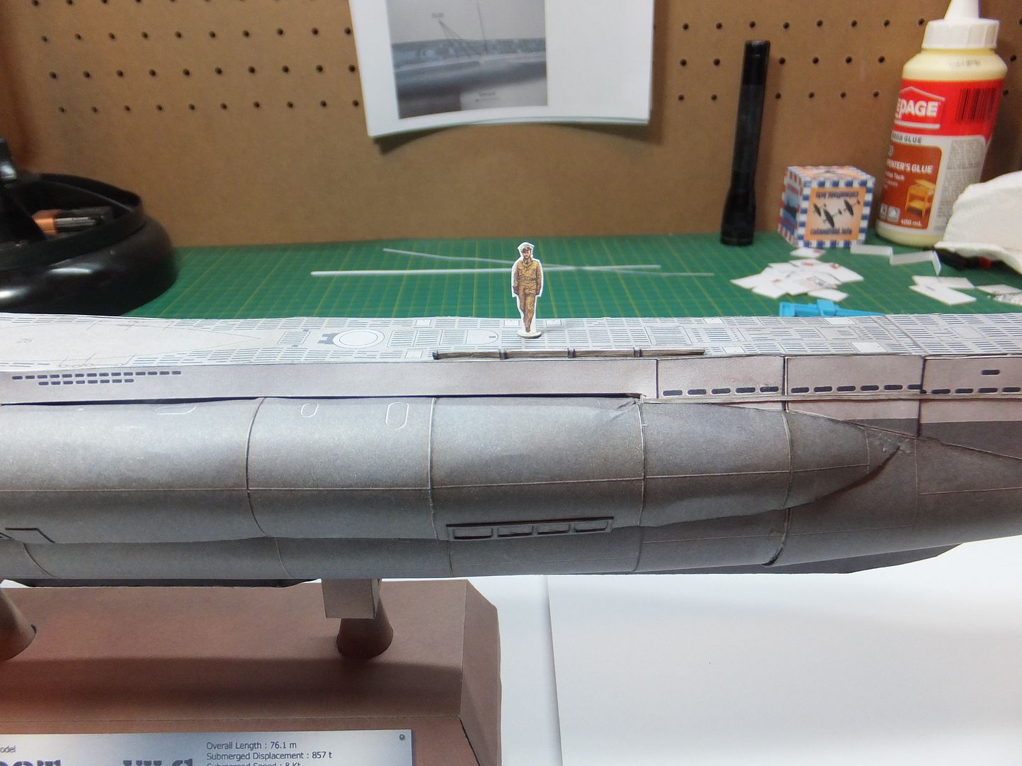
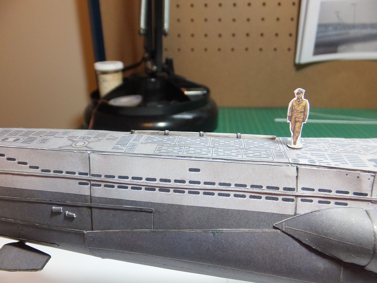
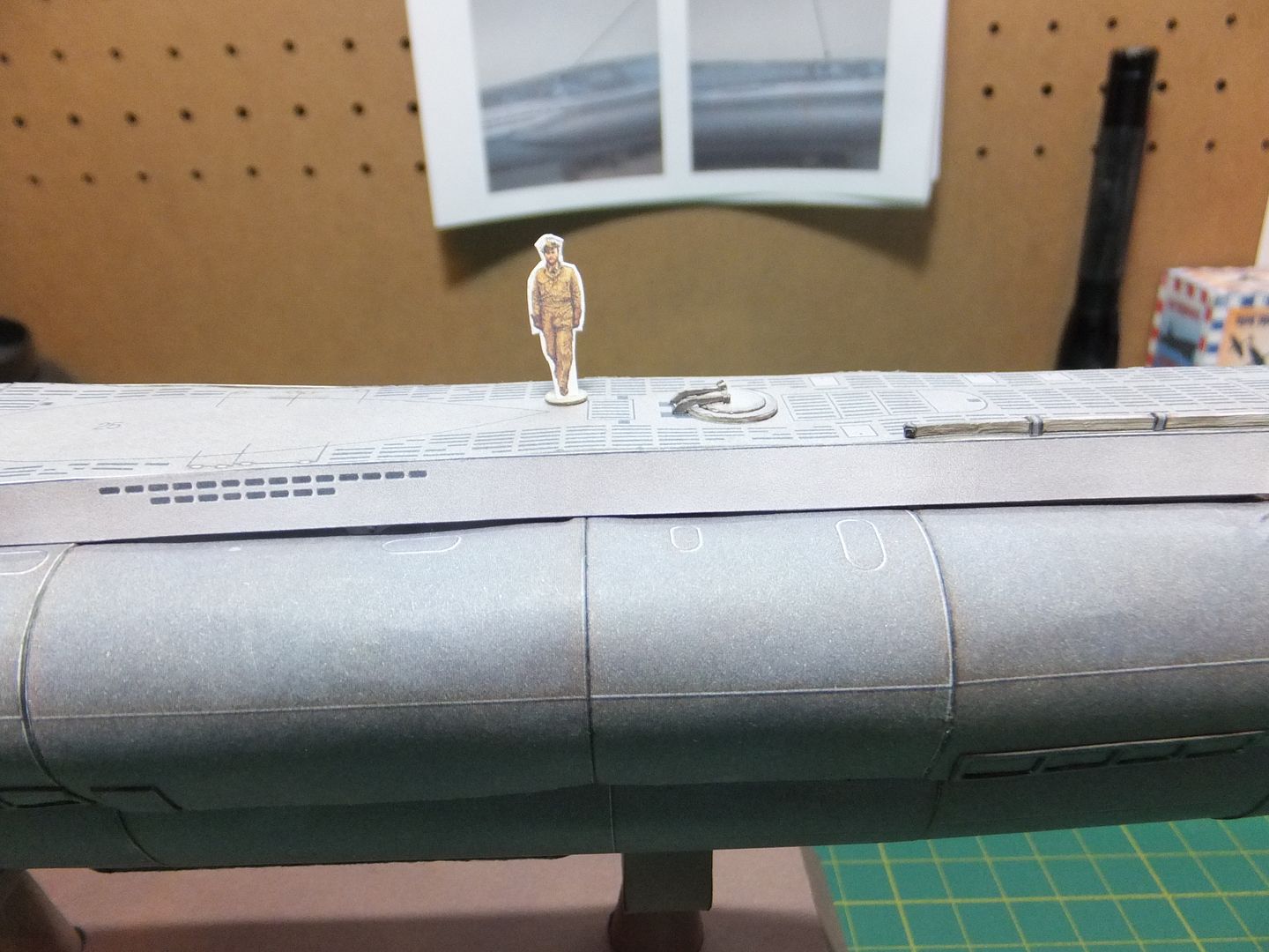
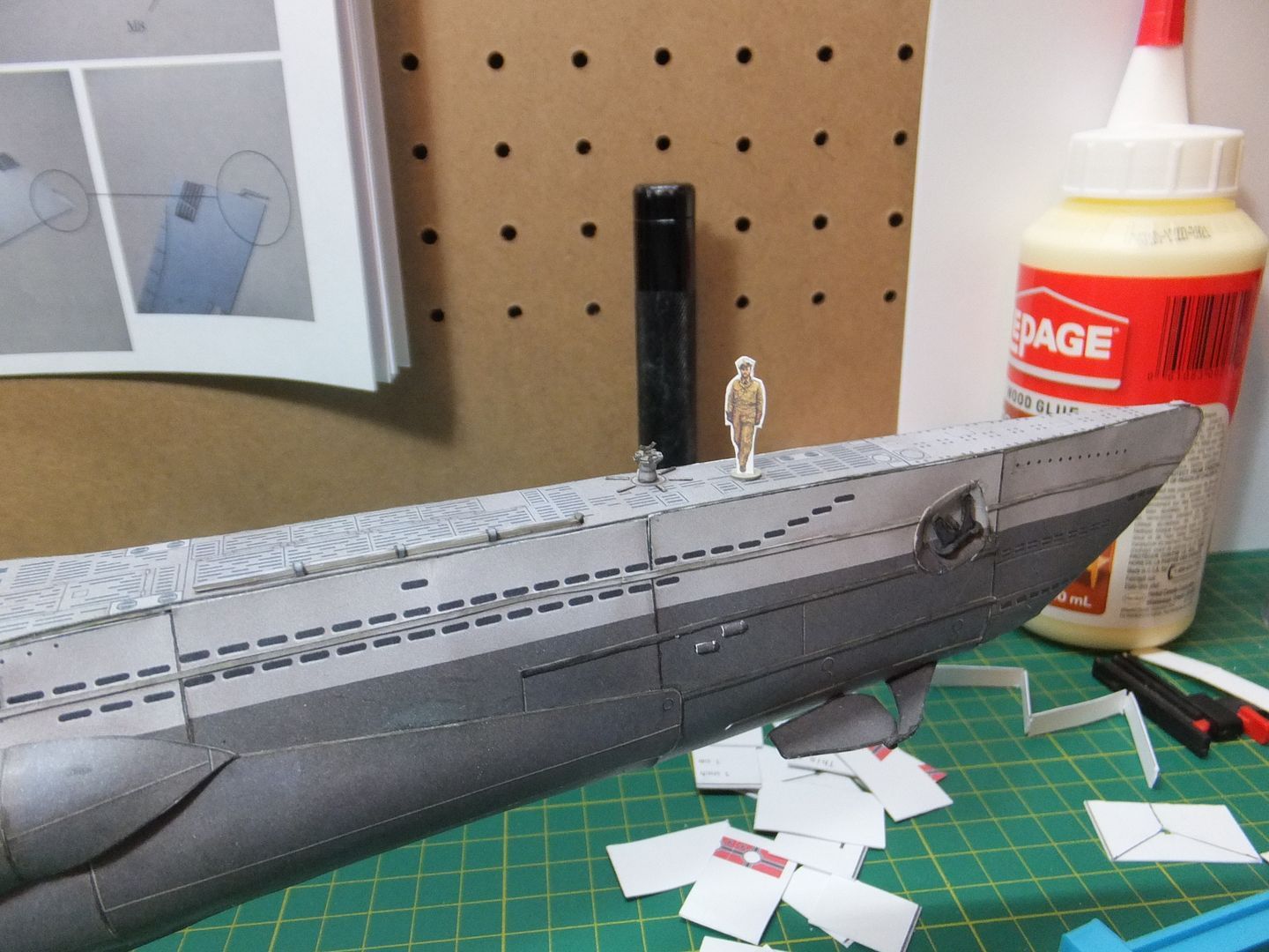
I brought on board Kapit. Fritz Lemp to oversee construction. ( He is in scale. )

KapitFritzJuliusLemp_zpscb41feae.jpg


You have to have some fun. ;D

Jim
 
Thanks Roy.
You can but if you are not handling it to much it will be fine. Some people seal the print before it is cut. I may try that in the future, but have not sealed any of my models yet.
I know this is a vague answer, but I hope it answers your question.

Jim
 
It's just rolling the paper into tubes. Either around a former ( some sort of round stock) or into a tight shaft. Then glue the seam. Not really that hard. I usually roll on top of an old mouse pad, it makes for smoother curves with less creases.

Jim
 
Hello.
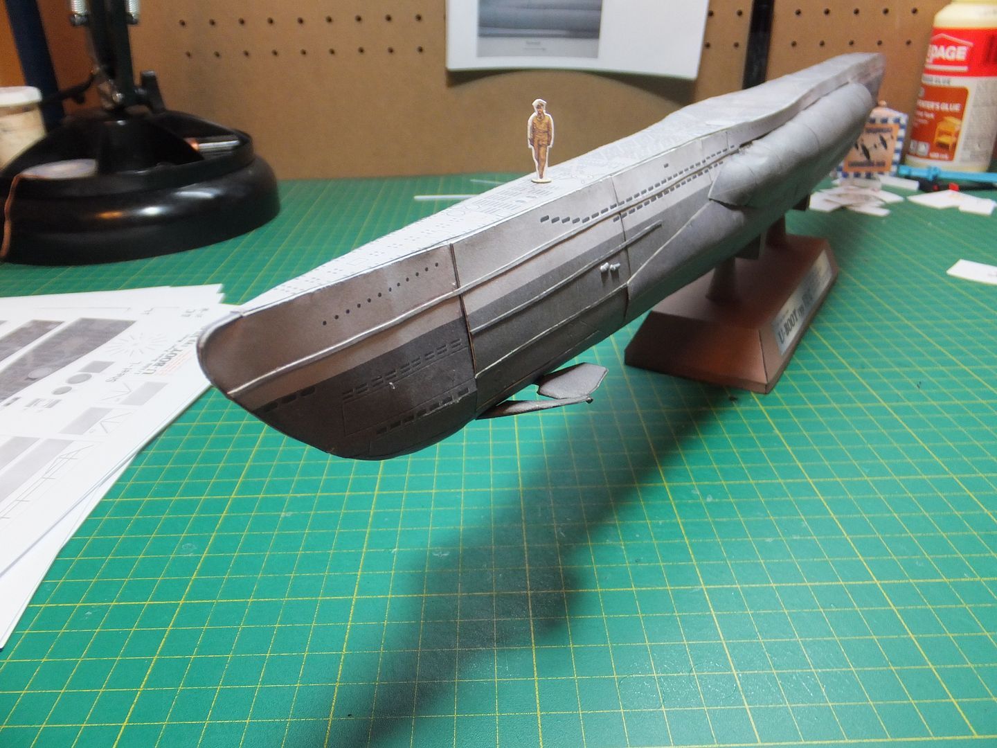
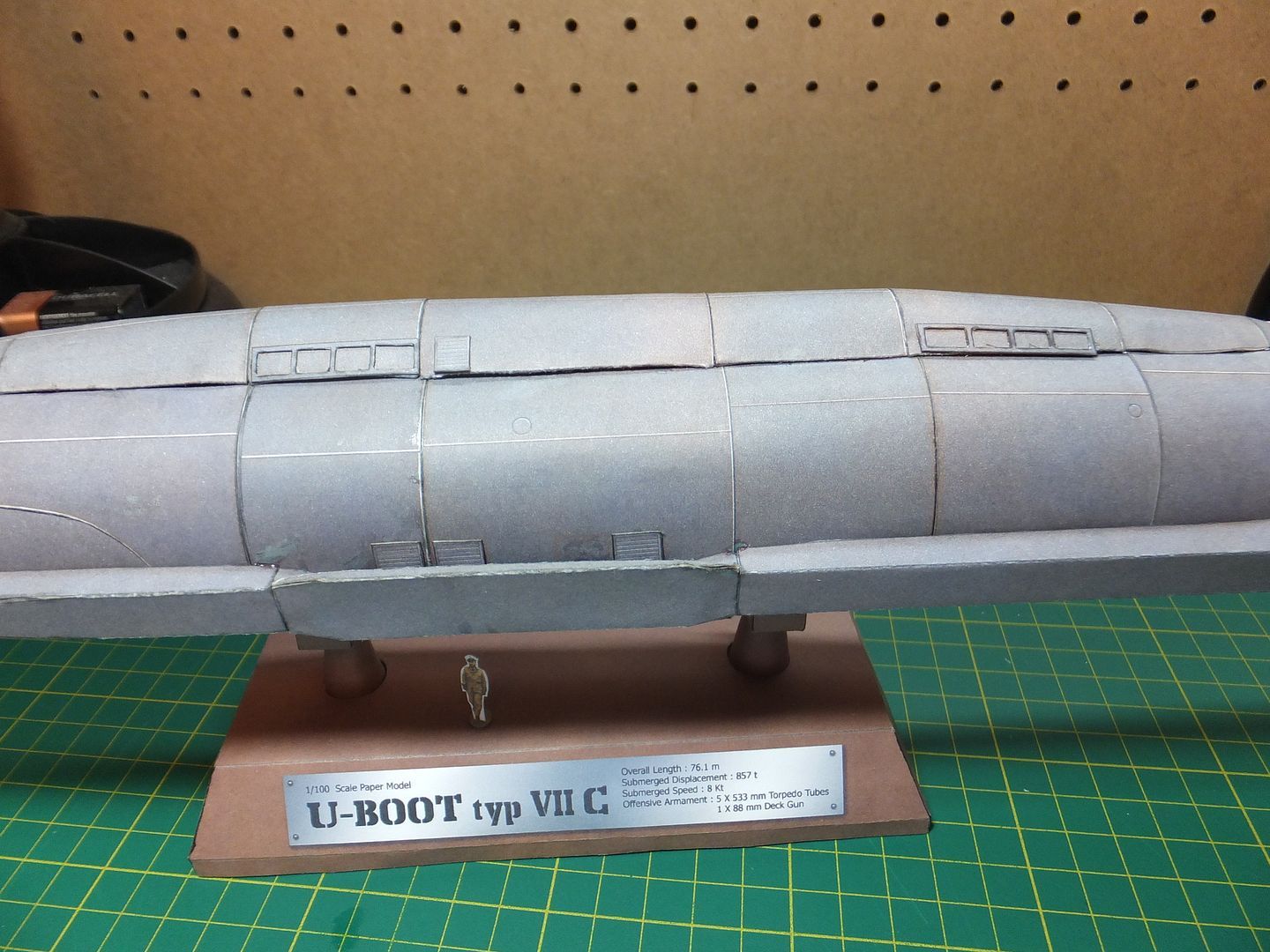
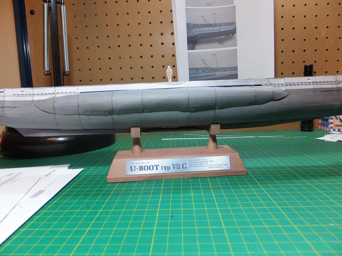
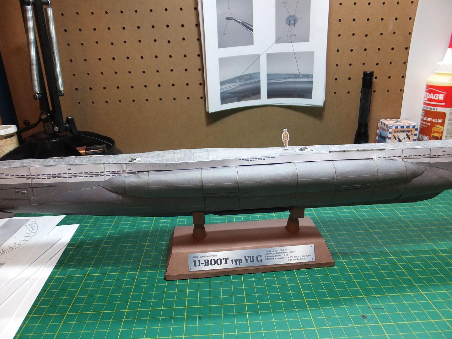
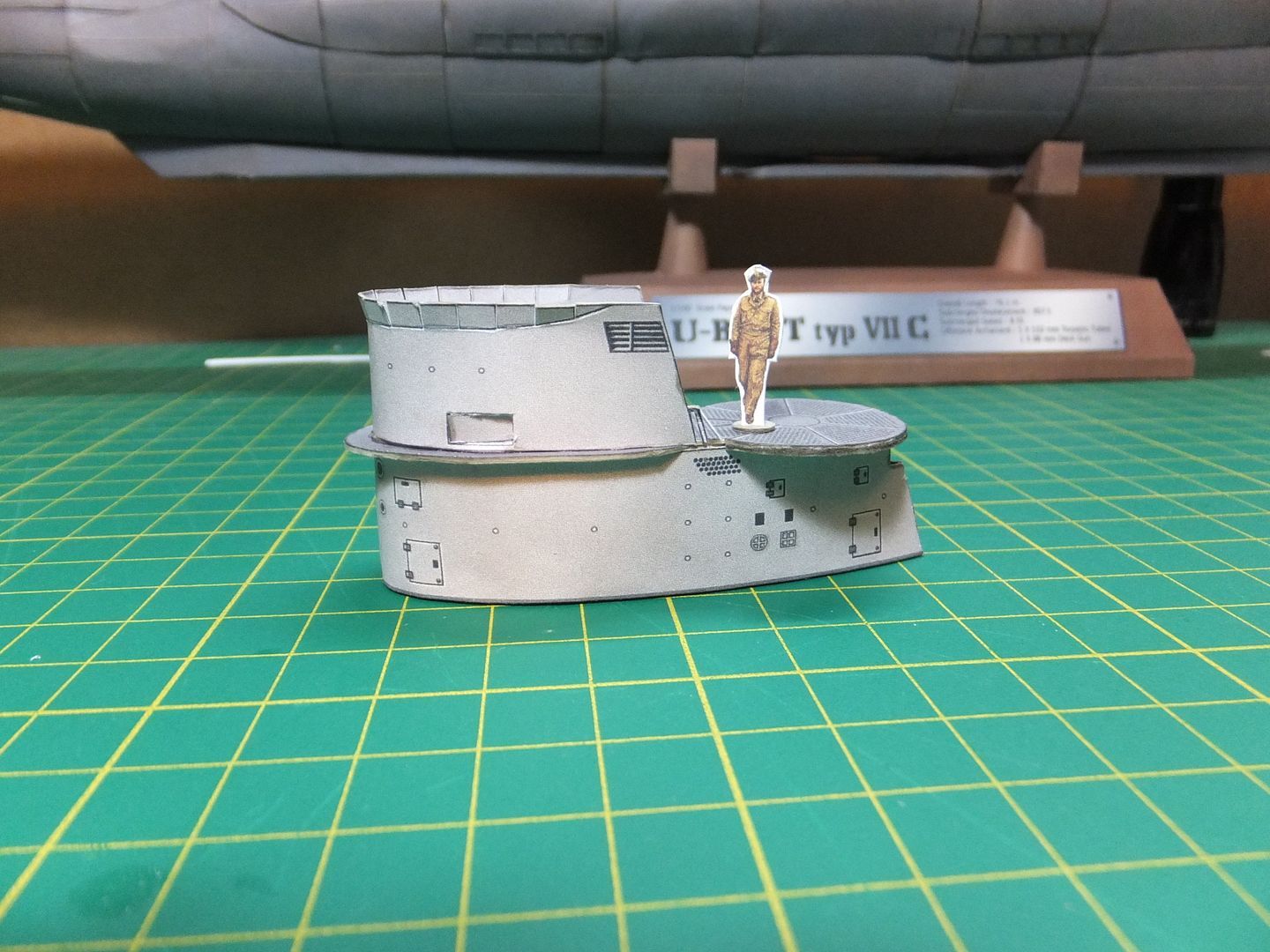
I find it interesting that as modelers we sometimes loose perspective on the size in real life the subjects we model really are. It was when I brought in the scale mannequin, the actual size of these subs became apparent. This is no small boat when compared to something we can relate to, size wise. Parts now seem enormous.
Today have been working on the forward dive planes and their support structure. These are now complete and installed.

Here the dive planes alone are dry fitted but not yet glued.

ForwardDivePlane2_zps7ea53cbb.jpg


Their outward support structures are here assembled. They will be dry fitted to the hull so that the planes may be positioned properly. Then the dive planes can be glued in position and these attached.

ForwardDivePlane3_zps8bb9e1d0.jpg


The forward dive plane assembly is now complete.

ForwardDivePlane4_zps409e1367.jpg


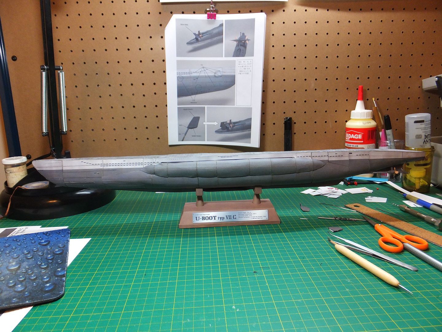
Again just an overall view of the ship as she stands tonight.

ForwardDivePlane5_zps6a2dc393.jpg


Tomorrow a couple of hull details to apply, then start on the main deck.

With this hobby I learn so much in the research for the model. Like, the last type VII was in service with the Danish navy till 1979 where upon it was sold to a German naval historical association for $0.60, and is now a museum. As well. after the war several of these were distributed to other navies including 2 to the Canadian Navy and used operationally. Over a hundred u-boats were scuttled after the war off the coast of Scotland.
Food for thought.

Have a good evening.

Jim
 
It's coming along really nicely Jim!

About sealing the model, I definitely encourage you to seal your next model, especially home-printed sheets with a lacquer coat or even an acrylic coat prior to cutting, I can attest to it working towards the modelers benefit. The coat makes cutting more crisp, allows for sanding edges without fear or fraying, and even the use of a bit of water to help form curves smoothly! :D
 
Thanks for the encouragement Fruit.


And thanks for the info. I know I should be sealing them. It's not like I don't have the materials, just haven't.

Jim
 
Nice job there Jim!! Those dive plane are tricky in plastic let alone paper! Keep at it!! ;)
 
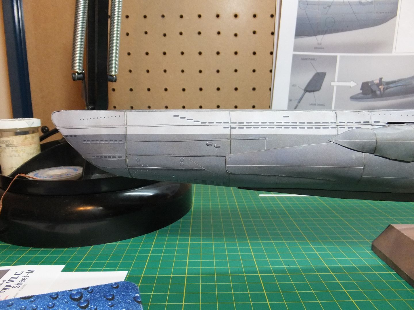
Today was able to finish off the detail items on the hull.

She's finally got an anchor.

HullDetail2_zpsc64cc23b.jpg


Finished of the addition of some vents to the hull.

HullDetail1_zpsfdc8e3ab.jpg


HullDetail3_zpsfd9cd208.jpg


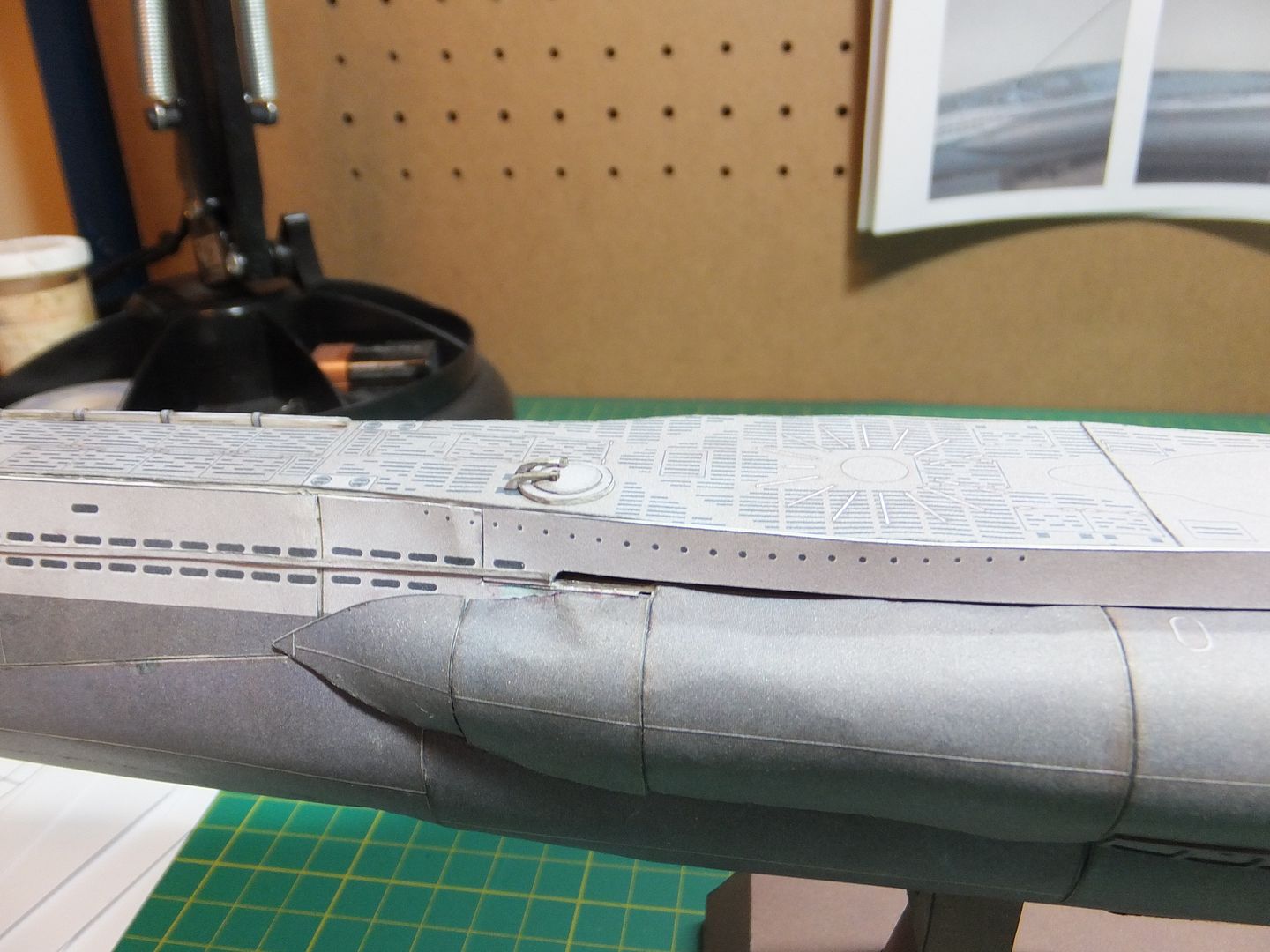
And was able to start adding some detail on deck. These are 4 layers of card as well, separate pieces for the straps.

DeckDetail1_zps95ba4eab.jpg


DeckDetail2_zps4c12c170.jpg


I think these are in reality wood to protect hoses used to refuel at sea.

Have a good day.

Jim
 
Hi Everyone. Short update.

Spent part of the day working on the hatches for the main deck.
Pieces had to be layered then had to wait till they dried before I could continue.
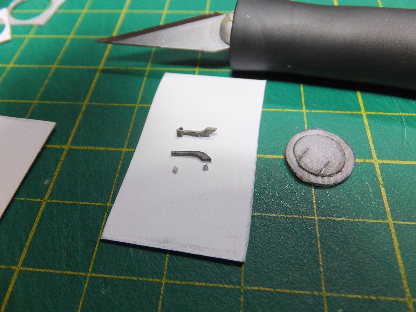
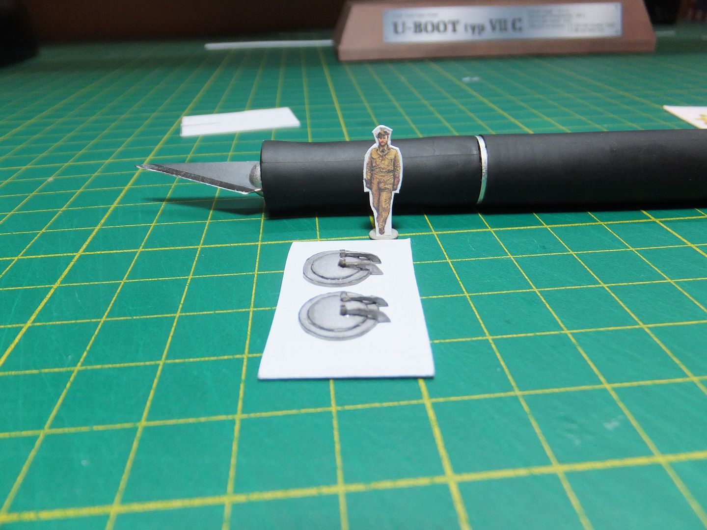
The doming (shaping) of the hatch was simple enough, but cutting out those hinges was a bit of a challenge. Those nuts for the hinges, now they were definitely a challenge.

Hatch1_zps2ae8cda5.jpg


I like the result of the hatches.

Hatch2_zpsd804d223.jpg


They were then installed in position.

Hatch3_zps16bc1586.jpg


Hatch4_zps963cb381.jpg


A view of the deck as she sits at the moment.

Hatch5_zps88b60e34.jpg


This process is slow, but I like how each piece brings more life to this model.

Jim
 
Tonight's update.
Added some more 3D detail to the main deck.

Aft.

DeckDetail3_zpsdcfe11a6.jpg


Forward as well. This main piece took the longest. It is constructed of 15 pieces, as well as 5 pieces to the raised deck feature.

DeckDetail4_zpsbceea48a.jpg


This afternoon was able to start on the conning tower. There is a lot of detail here, and is going to take a few days to complete.

Conning1_zps0449775c.jpg


The next while will be focused on the conning tower. Being box construction the lower section is quite sturdy. When gluing down it's deck, a hard cover book was placed on it to give downward pressure to keep it flat while drying.
That should be all for this evening.

Wishing the rest of you the best with your own builds.

Jim
 

Latest posts

Back
Top