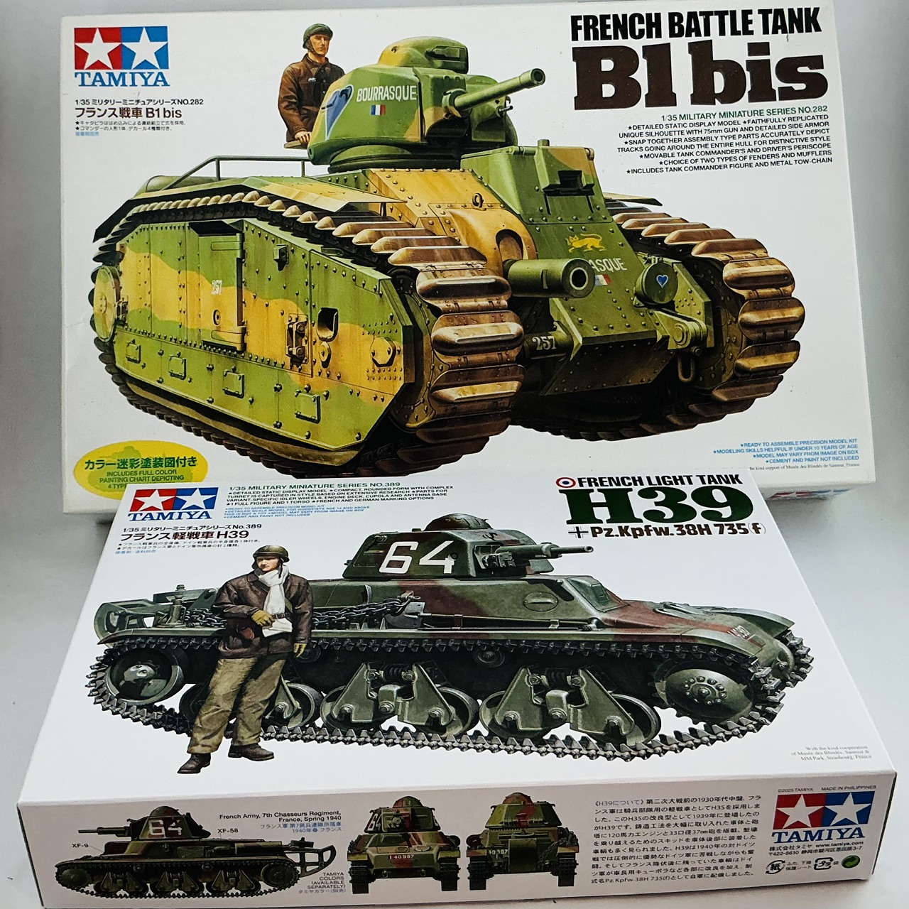
French tanks. But with a difference …

Scale Model Addict - Model Tips, Guides, Tools & Tech, Tutorials, and Community

Help Support Scale Model Addict:

Jakko

Well-Known Member
Joined
Oct 9, 2024
Messages
2,386
City & State/Province
Netherlands
Now that both Cuckoo and my Archer are nearly done, I think I can allow myself to start a topic about the next thing I will be building. Not one but two French tanks:

IMG_2679.jpeg


… but not quite as you might expect :)

IMG_2680.jpeg


About the how and why of this, I'll keep you wondering for a bit longer :P
 
Hmm … it's not going to be "ex-French, now British" — it will actually be more historical than that. Well, almost-historical, anyway …
 
As an Amazon Associate we earn from qualifying purchases. Product prices and availability are accurate as of the date/time indicated and are subject to change.
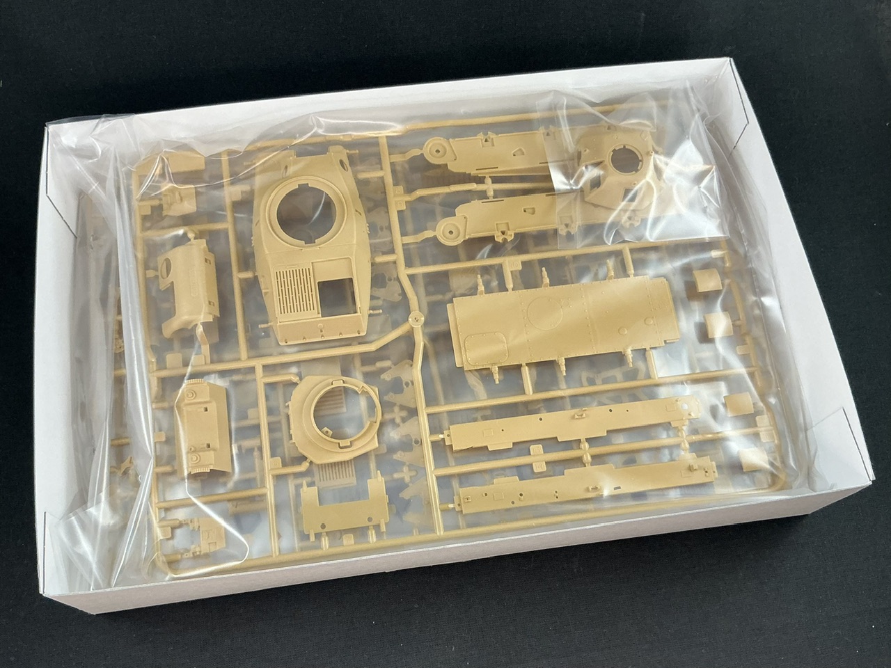
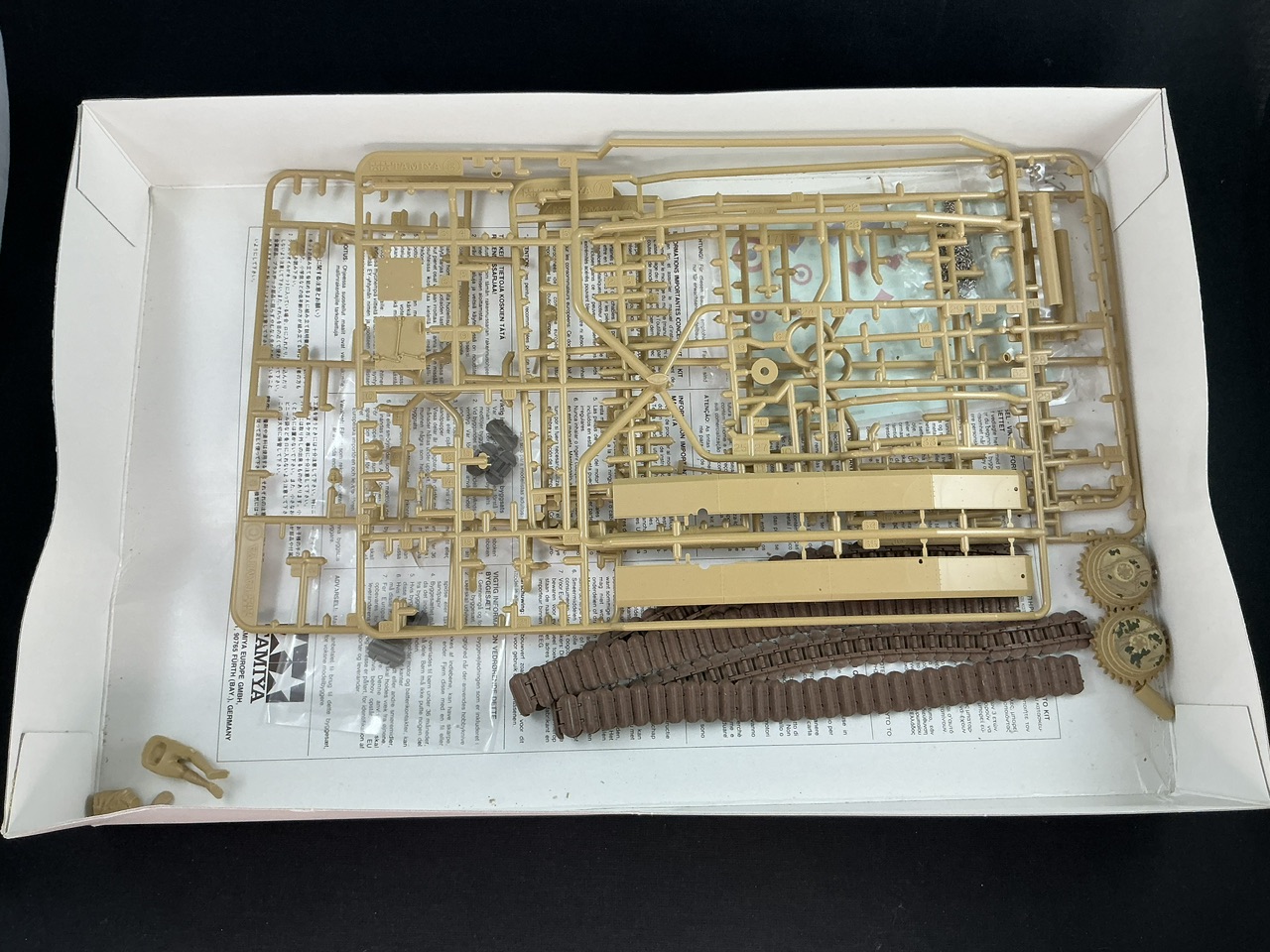
Let's start by showing the contents of the boxes. The H39 is, of course, brand-new and looks very good, as you would expect of modern Tamiya kits:

IMG_2696.jpeg


And the B1 bis:

IMG_2697.jpeg


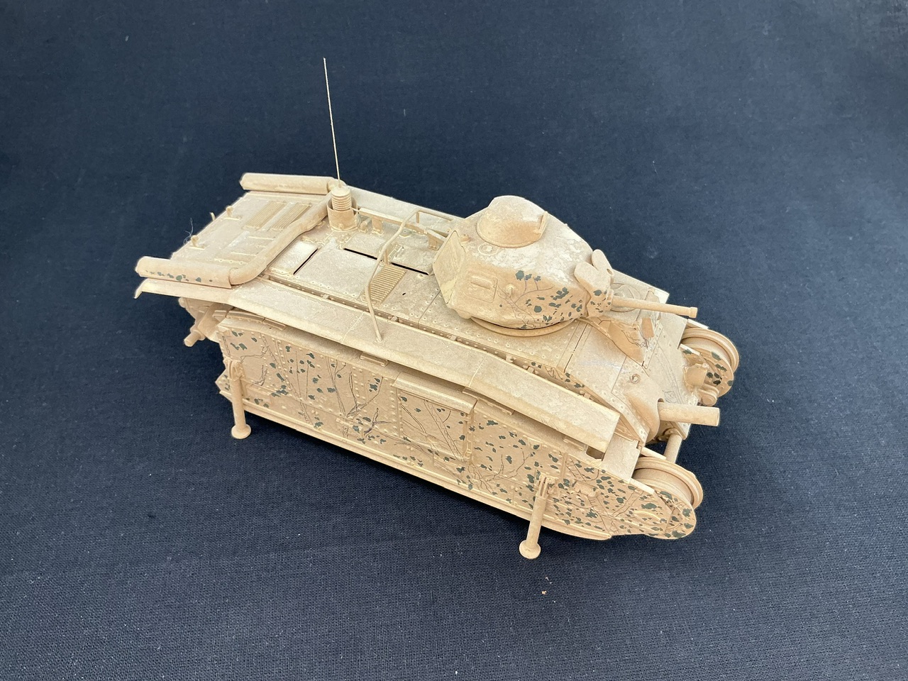
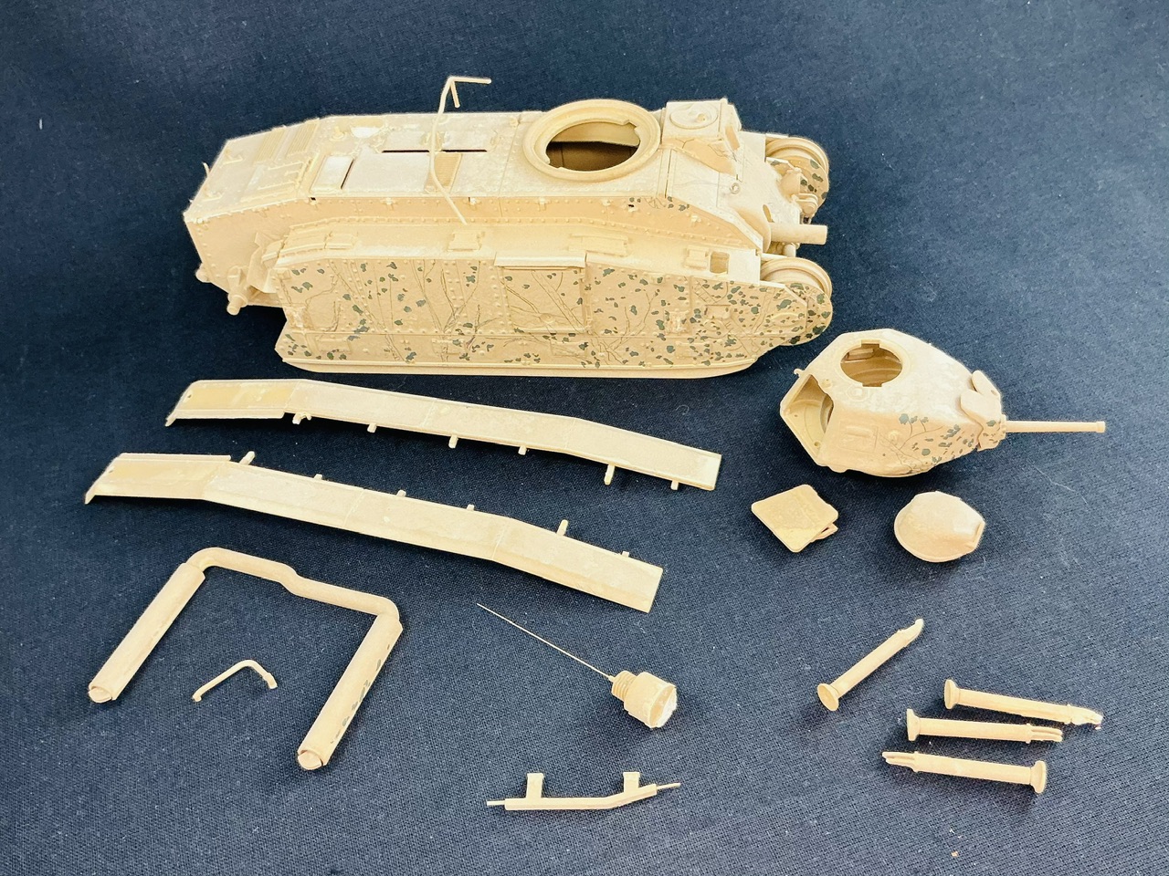
Um … Oh, yeah, I've had this for a bit longer, that's right … :) Almost twenty years ago, when it was new, I bought and built this kit, but never finished painting it:

IMG_2698.jpeg


As those knowledgeable about the B1 will already have spotted, the intention was to make it into tank No. 251, named Fantasque, but my artistic skills weren't up to doing justice to the painted-on trees and shrubs, which meant it ended up back in its box only to come out of it again now :)

The reason to do that and buy an H39 as well is:—
IMG_2610.jpeg


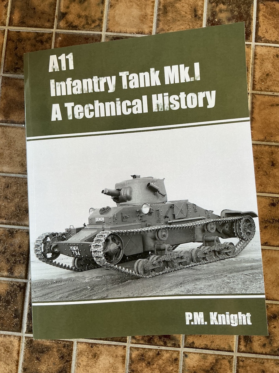
Because this has some interesting things to tell us about reasonably serious plans to cast armoured components for the H39 and/or Char B1 in the UK, in return for which the British would get completed tanks equal to half the number of castings they supplied. This never actually happened for several reasons, primarily of course the fall of France in June 1940, but also because the British were looking at making quite a few changes to make the H39 (the main candidate for this plan) better suited to their ways of armoured warfare. They wanted a two-man turret, for example, because they felt it needed more than one man (many French shared this opinion, but they were stuck with the turret, at least in the short run). There was also mention of doubling the number of bogies, but I can't figure out what exactly they meant by that — two side-by-side? I can't make much else of it, but it seems unlikely. There were also ideas about boring out the 37 mm gun to 39 mm so that it could fire British 2-pounder ammunition (a gun that today is considered a 40 mm, but in the late 1930s apparently a 39 mm).

In other words, this will be a what-if: What if the Battle of France had gone according to Franco-British plans so that the Germans would have been halted in northern France? and What if (because of this) French tanks had been supplied to the British in order to continue the war in France?.

The H39 will be built more or less straight from the box, with a few modifications. At the very least a British antenna, and probably reinforcing plates on all six bogies instead of only on the front ones or none at all, as Tamiya supplies them. And perhaps a hint that the gun uses 2-pounder ammunition.

The B1 bis will also get a British antenna and also a 2-pounder gun, because that was a better antitank gun than the French 47 mm and as far as I can tell, would fit in the turret. I also need to remove several parts that are already on the model, because Fantasque was a mid-production vehicle while the British would of course have gotten tanks with later features than that. Luckily, the details are on chars-francais.net.

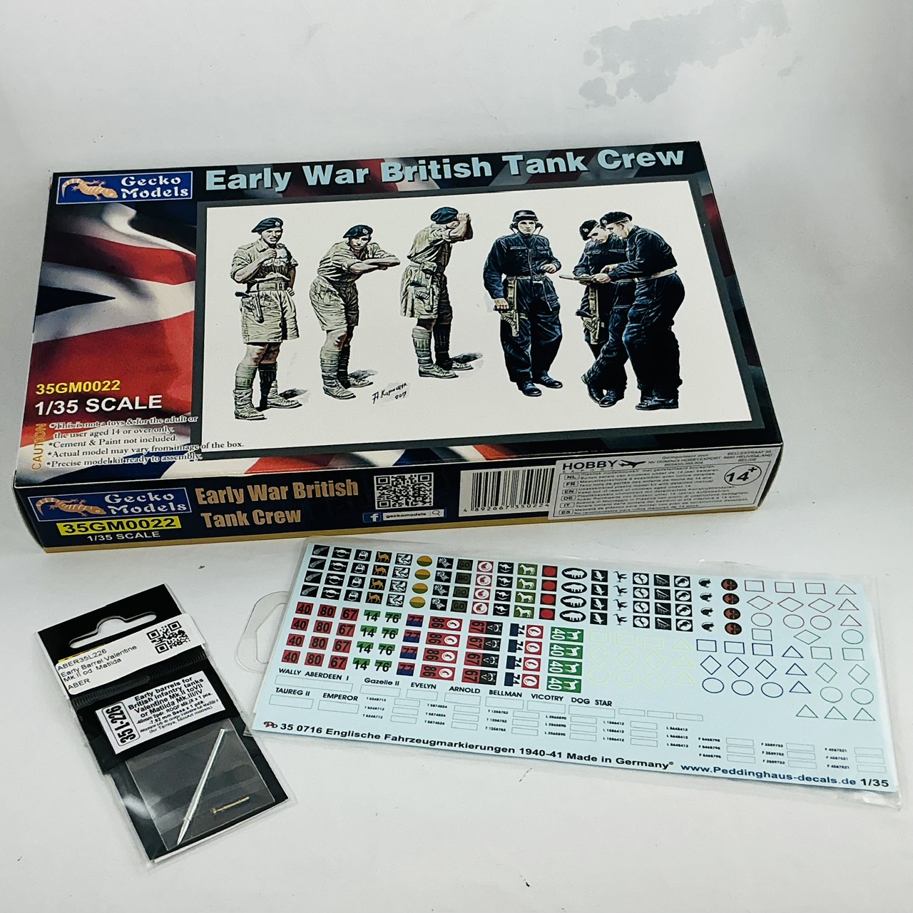
And, of course, British camouflage, markings and crews for both. That's what the Gecko figures and Peddinghaus decals are for :)
 
Last edited:
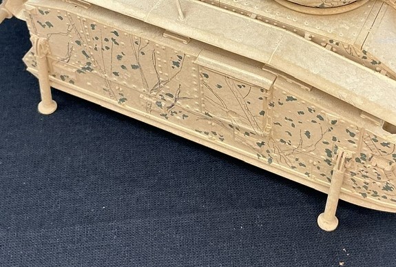
I'm not really sure what those are for either, but they're in the kit, and the instructions don't tell you about them at all. I can only speculate that they're for maintenance.
 
Haha .
I didn't see them in the pages you linked to . Figured you know all about them .
So disappointed in you Jakko . ;)

They indeed must be for dismounting that entire side plate , good lord , to access wheels / suspension .
Why did you install them if they aren't on Fantasque ?
 
Why did you install them if they aren't on Fantasque ?
They're clearly removable, not folding. The sides of the B1 bis have sockets with two horizontal bars (bolts?) that the legs fit into/onto, and I thought it would be more interesting to have them fitted. I still do, but I will be removing them for this British variant because I want to show it as in the field rather than undergoing repairs or something.
 
I cannot find a single photo of those yonkers attached to a B1
nor even a single scale model sporting them .
Do you have a photo or a technical description from a manual or the like ?

I was wondering if they carried it internal as standard kit . or , if that's depot gear .
 
I don't know either — like I said, they're in the kit but it doesn't tell you how to use them. However, they fit perfectly in the brackets on the hull sides, and I doubt Tamiya just made these up because they look nice :)

Anyway, they're off my model now, as I began work on the model by taking off the unnecessary bits tonight:

IMG_2700.jpeg


The turret, its hatch and the commander's cupola were loose anyway, the rest took a bit more effort. Not that much, because almost everything came off reasonably easily, except the antenna. I had to saw through that for about two-thirds of its diameter and then did the rest with a chisel-shaped knife, because there were details on the roof in the way of the saw. In doing this, I just managed to avoid stabbing myself in the fingers when the antenna gave way at the end of the— even though I was consciously trying to keep them out of the path of the blade! In other words: always beware.
 
I doubt Tamiya just made these up because they look nice
lulz , now I need to find out where Tamiya see them .
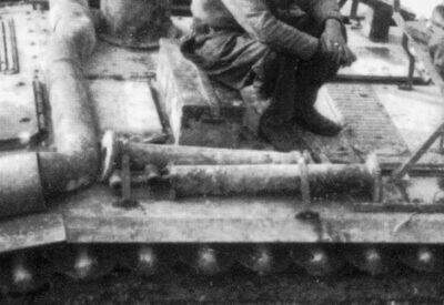
I'd think they would need to be screw jacks to be any real use . I can't see enough detail on them from your photo .
 
I think the idea is that the tank would have been jacked up, a strut installed, and the jack moved to another point to install another strut. This way the tank can be off the ground for work without there being jacks underneath it (never work under a vehicle if it's only supported by jacks).
 
Jakko, your models with the history behind are always interesting... Looking forward to this one! And question, how many more ideas do you have??
 
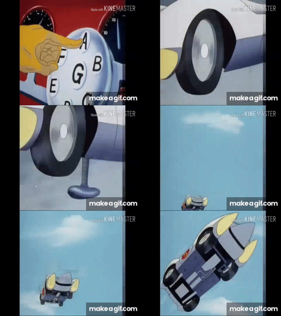
"not jack stands"
Literally candle sticks. Look at the photo I provided.
Top has two bolt attachment (so they lock in place, stay straight up and down).
Center is a straight tube with a large foot plate.
Obviously meant to support the side of the tank while a track is removed/replaced.
The vehicle must have carried a jack of some sort, however the supporting legs would only work on solid (pavement, concrete) ground.
 
M113 series had what we called a dog bone. It fit under the torsion arm and would lift said road wheel off the track for servicing. The tool would fit in at an angle, then the vehicle would move forward, and the bone would go vertical, lifting the assembly. For the life of me, I can't remember if the M109 series had something similar.
 
how many more ideas do you have??
Many :) A minor problem is that new ones usually come when I read or see interesting things, but always faster than I build the ones I'm already working on. And I often act on them according to the FIFO principe …


After taking the B1 apart, I had to clean up some more stuff before I could start rebuilding the model. In some of the holes for the mudguard locating pins, broken-off pieces of those pins remained, but I managed to get them out by giving them a tap using a punch and hammer from one of my punch-and-die sets. Unfortunately, I didn't notice in time that there are pins only at about half the locations of the mudguard supports on the real tank, leading me to think that there were also pins at the others that refused to come out, so I drilled those out. When I noticed my mistake, I had to fill them all with some putty again :)

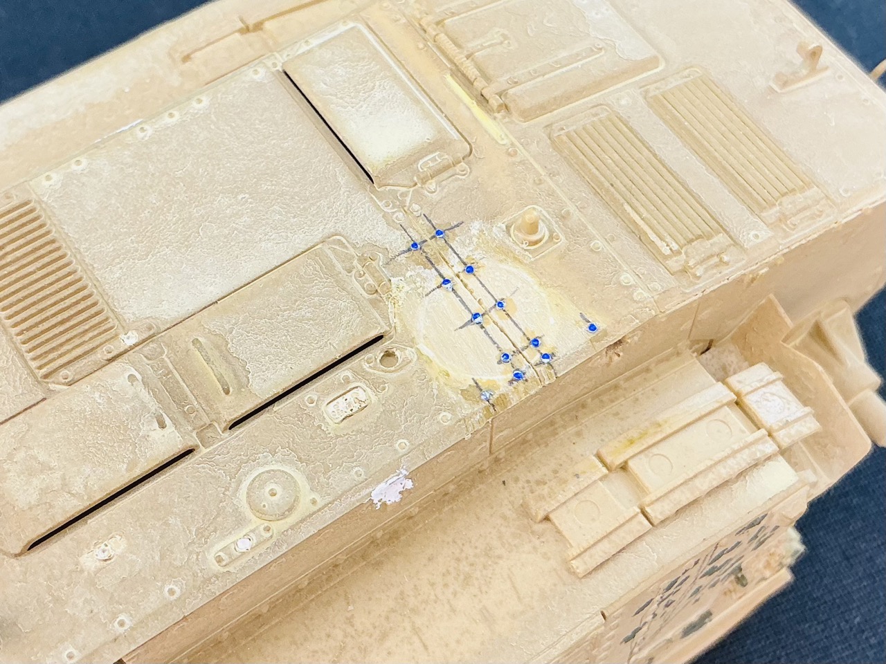
I then filed off the remains of the antenna base, losing a couple of rivets in the process, in addition to the ones that had to be cut away to fit the antenna back when I originally built this kit. Using the drawing in the instructions that tells you which rivets to remove for that, I could put all of them back after scribing the seam between the plates that was also lost by glueing the antenna over it:

IMG_2702.jpeg


The white dot is putty in an unnecessarily drilled hole :) The horrible patterns in the paint appeared as soon as I first sprayed the model way back when. I don't know what I did wrong, but I clearly did. That was another reason I put the model back into the box :)

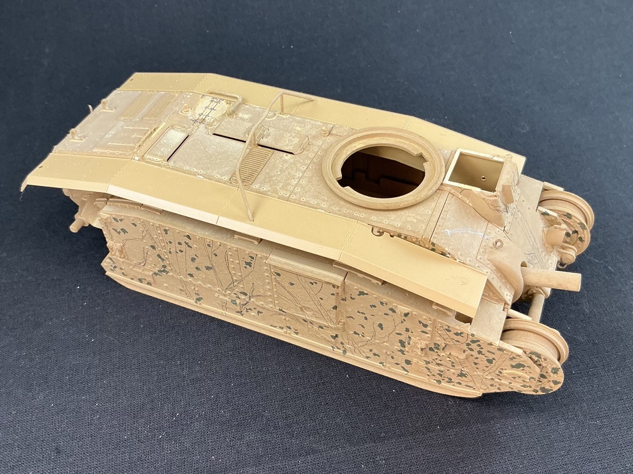
That done, I could fit the other mudguards:

IMG_2703.jpeg


I had also completely taken off the fence on the hull top (which serves to prevent the turret guns from shooting up the back of the tank), but it fit neatly back in place. I also took off the driver's hatch, as I intend to replace that with another.
 
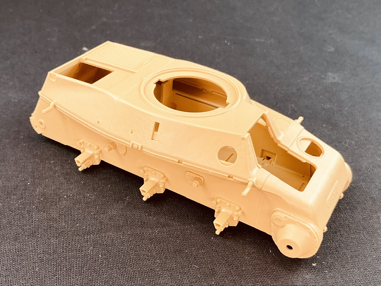
By now I've also started on the H39:

IMG_2704.jpeg


The upper hull is still loose, it's only on to make sure the lower hull is correct. But it's very obvious that this is a brand-new Tamiya kit: everything simply fits as it should, not too loose but also not too tight like you get with many Chinese brands.
 
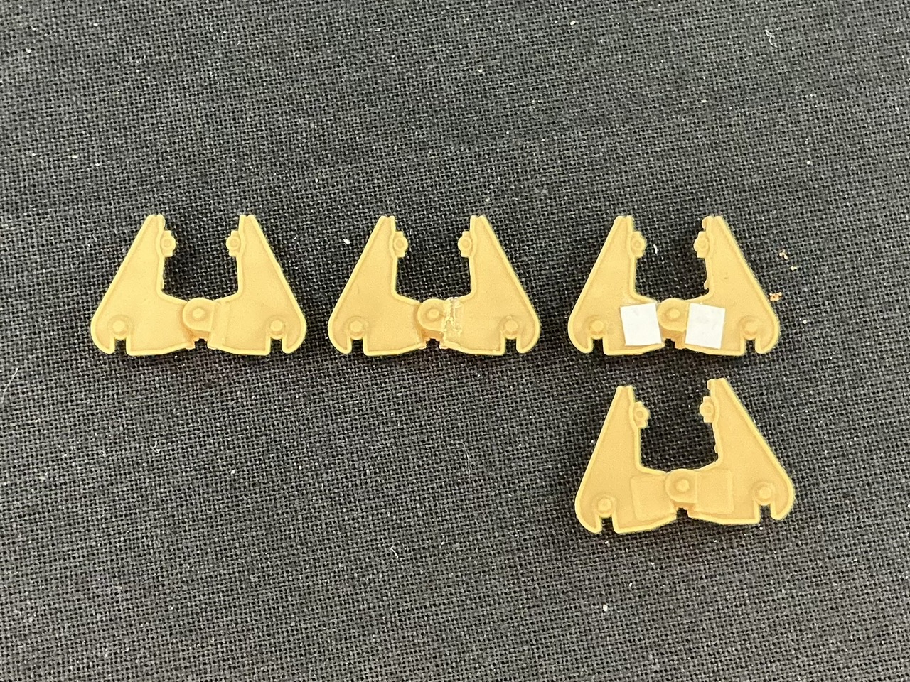
The real H39 had a number of variations in the bogies: without reinforcing plates welded to the wheel arms, or with a few different sizes of those. I'm under the impression (based on asking about this on Missing-Lynx) that this plate was enlarged over time to make the wheel arms sufficiently strong. When the Germans rebuilt H39s, they put them on the front wheel stations, while in French service they could be on one, two or all three stations per side. But Tamiya only gives two reinforced bogies with a large plate on both arms and six with only a small plate on one arm per bogie. Because I figure the speculative British H39s would have had the latest improvements that were in production in 1940, I wanted a large plate on all of the wheel arms. That required a little cutting so I could glue bits of 0.25 mm plastic card, 4 mm high and 3.5 mm wide, to the wheel arms:

IMG_2705.jpeg


At left an unmodified part, in the middle one from which I've cut away the small plate, at upper right one with both plates glued on, and below that a kit part with those plates. I didn't use that last one because I don't want there to be an obvious difference between the kit parts and the converted ones. Another way, of course, is to ask two people for their leftover parts :)

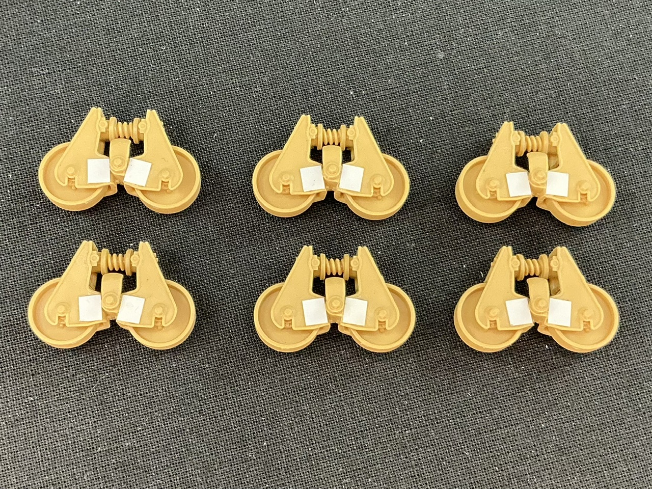
Here's all six modified bogies:

IMG_2706.jpeg


I only glued the plates to the outside, because those on the inside would be all but invisible. I think I might smear a little putty along the edges to replicate the welds around the plates.

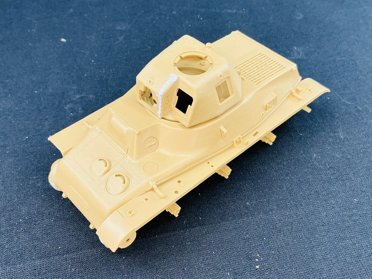
The hull is now largely done and the basic turret shape is also together:

IMG_2707.jpeg


I'm undecided whether to fit the trench skid on the rear of the hull. It's exactly the kind of thing that the British Army's higher-ups might have decided is unnecessary, and which tank crews then later wished they had it :)
 
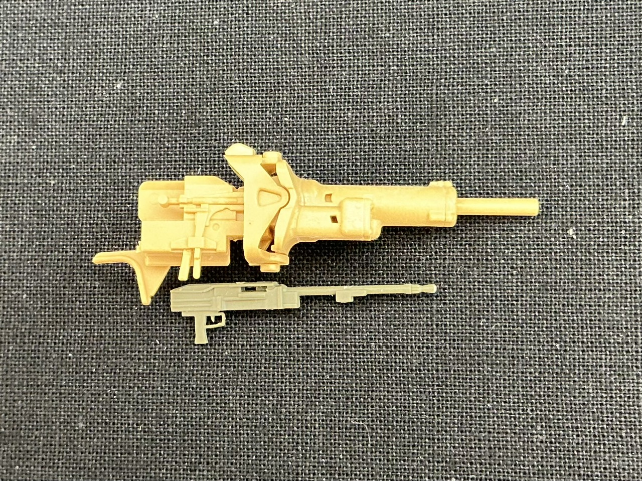
A British tank won't have had a French machine gun, but does a Besa fit in the H39's gun shield?

IMG_2716.jpeg


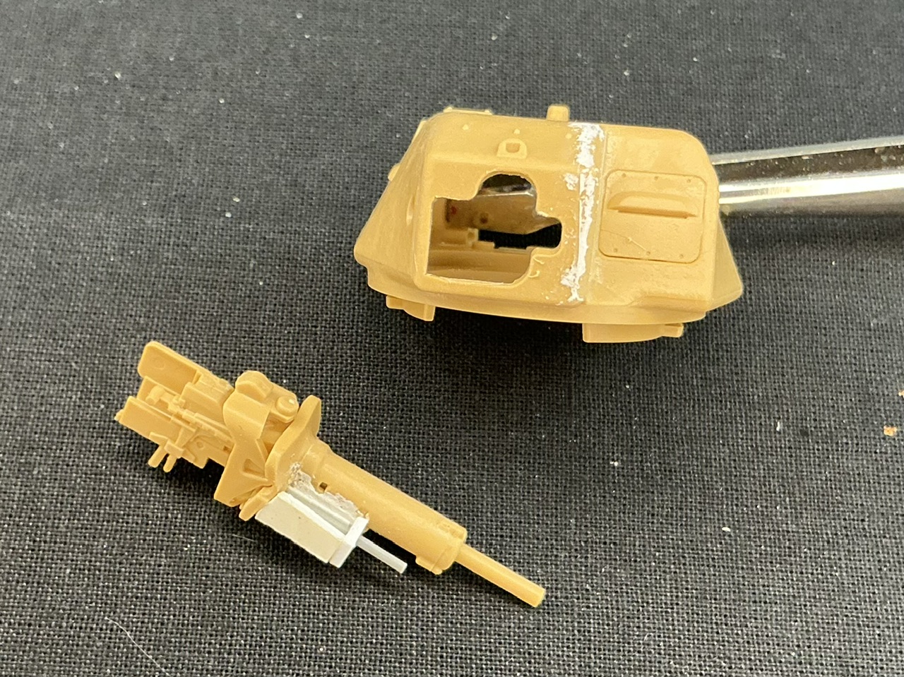
It looks like it could fit more or less as the photo shows (but next to the gun, of course :) ), with the forward end of the barrel sticking out beyond the armour that has been made to protect the barrel of the French MAC 1931. Except I don't think a Besa would fit inside that, because it's a pretty wide weapon with large protective plates alongside the barrel at the front of the receiver (missing on the gun in the photo). On British tanks, the Besa was normally mounted in a kind of "trough" that is open at the top, I assume for better cooling. Some measuring, though, proved that such a trough can be fitted here, too:

IMG_2718.jpeg


I first cut away the upper, side and front parts of the French "barrel guard". The barrel is a piece of plastic rod left over from a kit, with a little block of plastic glued underneath for the protective plates to be stuck onto, which were made from plastic strip. I next added some thin plastic card and putty on the left, to close the gap towards the 37 mm gun barrel, then glued the barrel in place, made the right-hand side from 0.75 mm and the front from 1 mm plastic card. The glue on this now has to dry before I can scrape and putty it all a bit so it will look more like a single-piece casting with the rest of the gun shield.

Only thing is that this has made the shield here wider and taller than the original, which prevents it from fitting into the turret. This, I solved by filing out the opening in the front plate to the right and up until the gun fits and can elevate as it should. You can't really tell this from the photo because I forgot to take a "before" picture, but if you compare it to pictures of a non-converted model, it should be obvious :)
 
Why remake the entire MG box instead of just replacing the barrels?

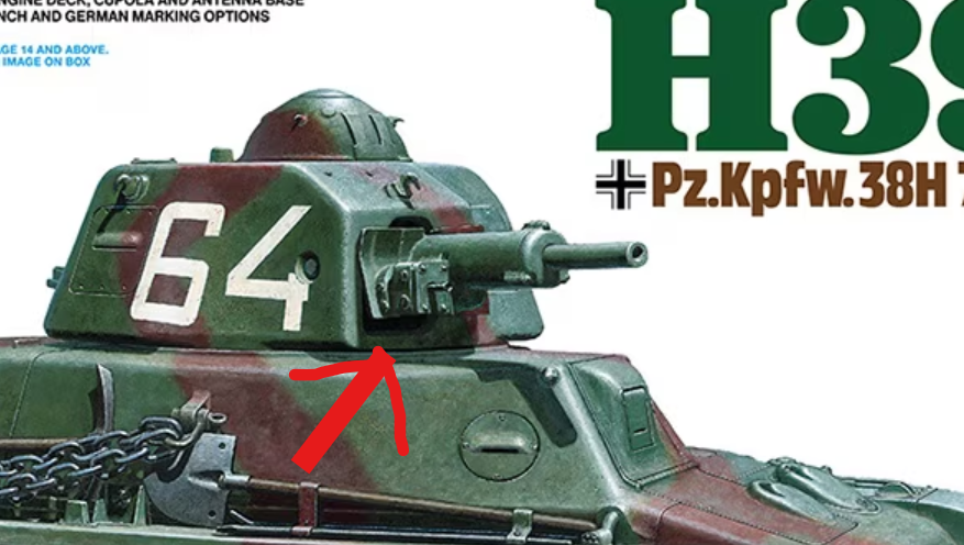
It is this part, right?

1747778198542.png
 

Latest posts

Back
Top