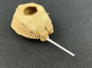
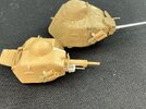
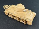
French tanks. But with a difference …

"not jack stands"
Literally candle sticks. Look at the photo I provided.
Top has two bolt attachment (so they lock in place, stay straight up and down).
Center is a straight tube with a large foot plate.
Obviously meant to support the side of the tank while a track is removed/replaced.
The vehicle must have carried a jack of some sort, however the supporting legs would only work on solid (pavement, concrete) ground.
 
M113 series had what we called a dog bone. It fit under the torsion arm and would lift said road wheel off the track for servicing. The tool would fit in at an angle, then the vehicle would move forward, and the bone would go vertical, lifting the assembly. For the life of me, I can't remember if the M109 series had something similar.
 
how many more ideas do you have??
Many :) A minor problem is that new ones usually come when I read or see interesting things, but always faster than I build the ones I'm already working on. And I often act on them according to the FIFO principe …


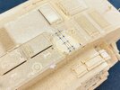
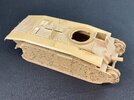
After taking the B1 apart, I had to clean up some more stuff before I could start rebuilding the model. In some of the holes for the mudguard locating pins, broken-off pieces of those pins remained, but I managed to get them out by giving them a tap using a punch and hammer from one of my punch-and-die sets. Unfortunately, I didn't notice in time that there are pins only at about half the locations of the mudguard supports on the real tank, leading me to think that there were also pins at the others that refused to come out, so I drilled those out. When I noticed my mistake, I had to fill them all with some putty again :)

I then filed off the remains of the antenna base, losing a couple of rivets in the process, in addition to the ones that had to be cut away to fit the antenna back when I originally built this kit. Using the drawing in the instructions that tells you which rivets to remove for that, I could put all of them back after scribing the seam between the plates that was also lost by glueing the antenna over it:

IMG_2702.jpeg

The white dot is putty in an unnecessarily drilled hole :) The horrible patterns in the paint appeared as soon as I first sprayed the model way back when. I don't know what I did wrong, but I clearly did. That was another reason I put the model back into the box :)

That done, I could fit the other mudguards:

IMG_2703.jpeg

I had also completely taken off the fence on the hull top (which serves to prevent the turret guns from shooting up the back of the tank), but it fit neatly back in place. I also took off the driver's hatch, as I intend to replace that with another.
 
By now I've also started on the H39:

IMG_2704.jpeg

The upper hull is still loose, it's only on to make sure the lower hull is correct. But it's very obvious that this is a brand-new Tamiya kit: everything simply fits as it should, not too loose but also not too tight like you get with many Chinese brands.
 
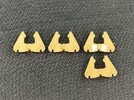
The real H39 had a number of variations in the bogies: without reinforcing plates welded to the wheel arms, or with a few different sizes of those. I'm under the impression (based on asking about this on Missing-Lynx) that this plate was enlarged over time to make the wheel arms sufficiently strong. When the Germans rebuilt H39s, they put them on the front wheel stations, while in French service they could be on one, two or all three stations per side. But Tamiya only gives two reinforced bogies with a large plate on both arms and six with only a small plate on one arm per bogie. Because I figure the speculative British H39s would have had the latest improvements that were in production in 1940, I wanted a large plate on all of the wheel arms. That required a little cutting so I could glue bits of 0.25 mm plastic card, 4 mm high and 3.5 mm wide, to the wheel arms:

IMG_2705.jpeg

At left an unmodified part, in the middle one from which I've cut away the small plate, at upper right one with both plates glued on, and below that a kit part with those plates. I didn't use that last one because I don't want there to be an obvious difference between the kit parts and the converted ones. Another way, of course, is to ask two people for their leftover parts :)

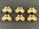
Here's all six modified bogies:

IMG_2706.jpeg

I only glued the plates to the outside, because those on the inside would be all but invisible. I think I might smear a little putty along the edges to replicate the welds around the plates.

The hull is now largely done and the basic turret shape is also together:

IMG_2707.jpeg

I'm undecided whether to fit the trench skid on the rear of the hull. It's exactly the kind of thing that the British Army's higher-ups might have decided is unnecessary, and which tank crews then later wished they had it :)
 
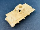
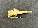
A British tank won't have had a French machine gun, but does a Besa fit in the H39's gun shield?

IMG_2716.jpeg

It looks like it could fit more or less as the photo shows (but next to the gun, of course :) ), with the forward end of the barrel sticking out beyond the armour that has been made to protect the barrel of the French MAC 1931. Except I don't think a Besa would fit inside that, because it's a pretty wide weapon with large protective plates alongside the barrel at the front of the receiver (missing on the gun in the photo). On British tanks, the Besa was normally mounted in a kind of "trough" that is open at the top, I assume for better cooling. Some measuring, though, proved that such a trough can be fitted here, too:

IMG_2718.jpeg

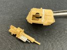
I first cut away the upper, side and front parts of the French "barrel guard". The barrel is a piece of plastic rod left over from a kit, with a little block of plastic glued underneath for the protective plates to be stuck onto, which were made from plastic strip. I next added some thin plastic card and putty on the left, to close the gap towards the 37 mm gun barrel, then glued the barrel in place, made the right-hand side from 0.75 mm and the front from 1 mm plastic card. The glue on this now has to dry before I can scrape and putty it all a bit so it will look more like a single-piece casting with the rest of the gun shield.

Only thing is that this has made the shield here wider and taller than the original, which prevents it from fitting into the turret. This, I solved by filing out the opening in the front plate to the right and up until the gun fits and can elevate as it should. You can't really tell this from the photo because I forgot to take a "before" picture, but if you compare it to pictures of a non-converted model, it should be obvious :)
 
Why remake the entire MG box instead of just replacing the barrels?

It is this part, right?

1747778198542.png
 
I explained that:—
I don't think a Besa would fit inside that, because it's a pretty wide weapon with large protective plates alongside the barrel at the front of the receiver
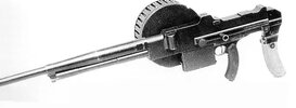
:)

The MAC 1931, that the housing on the H39 is designed for, is a very slender gun forward of the receiver:

MAC 1931.jpeg

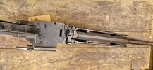
But the Besa is wide:

Besa.jpeg

It has those guards, or whatever they're supposed to be (supports for the forward end of the barrel, I think), along about half the barrel. What's more, those are not removable — they're an integral part of the receiver, for some reason.
 
I explained that:—

:)

The MAC 1931, that the housing on the H39 is designed for, is a very slender gun forward of the receiver:


But the Besa is wide:


It has those guards, or whatever they're supposed to be (supports for the forward end of the barrel, I think), along about half the barrel. What's more, those are not removable — they're an integral part of the receiver, for some reason.

The reason is the mass of the barrel ,

 
I also came across that video but haven't actually watched it other than to show someone on another forum how the barrel is removed :)
 
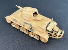
The H39 is now mostly done:

IMG_2721.jpegIMG_2722.jpeg

I glued the extra shields around the armament, but of course had to cut the one on the right-hand side back a bit to fit over the new machine-gun mounting. The tools are partly from the kit, but all the green plastic is from an AFV Club Churchill, because I think the British would have wanted British pioneer tools on the tank. The rest of the green is paint, brushed into areas that will be hard to reach with an airbrush later.

What's still missing is four things: e British antenna (base), a British tow cable (rather than a French chain)m, the towing eyes and British smoke launchers. The latter are easy enough to make, except for the slight snag that I haven't found any tube or similar of a suitable diameter yet.

On the B1 bis, I sawed the gun from the turret and replaced it by an Aber 2-pounder barrel:

IMG_2723.jpeg

That only just worked, because the new barrel is 2.8 mm thick and the plastic of the old one is about 3 mm. It's actually only attached to a sliver of the old barrel that's wrapped around maybe half the barrel …

Incidentally, the muzzle is 30 mm in front of the gun shield. That's less than the full length of the Aber barrel, because I worked out from drawings how far it should go to have the trunnions in the same location as for the original 47 mm SA 38 gun.
 
I've been making British smoke grenade dischargers today:

IMG_2724.jpeg

After a lot of searching for suitable diameter pipe to make them from, I discovered that parts of the H39 sprue have approximately the correct diameter (which is 3.3 mm). I first drilled a 2 mm hole into this, then reamed it out to almost the full diameter with a sharp knife. The firing mechanism was made just like the real thing: by cutting down Lee-Enfield rifles :) The bracket is just some plastic card cut to size and glued to the turret. It still needs cables added from the trigger guards to a hole somewhere in the turret.

On the B1, I also added the Besa barrel that came in the Aber set with the 2-pounder. It simply sticks out from the B1's gun shield here, because by holding the plastic Besa next to the turret, it looks like there would have been enough space to have installed it this far forward on the real tank.
 
The later version of these had a dedicated firing mechanism — but that looks like it was designed by the same person who designed the Sten, and for some odd reason still has an external trigger …
 
I'm assuming they had a way of actually firing those smoke grenade dischargers from inside the tank right? Some poor sod didn't have to lean over the side and pull the Lee-Enfield triggers himself? I mean, it wouldn't surprise me if that WAS the case - knowing how Heath Robinson most British engineering can be.

Perhaps they tied a bit of string around the triggers and fed them through the commander's hatch :D


Write your reply...

Latest posts

Back
Top