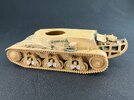
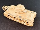
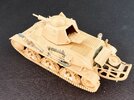
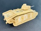
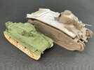
French tanks. But with a difference …

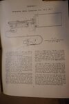
No, no, they weren't that stupid :) The way they work is, a bicycle brake cable was attached to the trigger guard and trigger, running inside the turret, where there was a bicycle brake lever that the commander squeezed to fire them. Very Heath Robinson indeed :)
 
Last edited:
Brake cables? Seriously? Well I suppose if it works it works - even if it is only one up from string LOL!
 
Well, Bowden cables, really. But bicycle brake cables are nearly invariably Bowden cables, and since they appear to have used an actual brake lever at the end of it, chances are good they used actual brake cables, too. I mean, they were in production, available and can be made to pretty much any length required very easily.

Here's a page from an official manual, with thanks to Rob Love over on Maple Leaf Up:

DSC00152.jpg
 
That's a great illustration - thanks Jakko. Simple and gets the job done I suppose, which is fair enough.
 
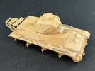
On the H39, I added two tow cables:

IMG_2810.jpeg

These are cable eyes from (IIRC) a Tamiya Sd.Kfz. 221 with nylon string between them to make a total length of 12.5 cm, which is approximately the scale length of such British tow cables. They're just a bit too short to allow them to be fastened to the front and rear towing eyes, though, so I put them on the middle one instead, which seems a reasonable way to stow them to me.

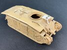
For the B1, the brilliant idea (yes, indeed …) came to me that by 1941, the tank might well have been welded instead of riveted in order to simplify production and increase protection against enemy fire. I used a couple of different knives to chisel, cut and scrape away a whole bunch of rivets:

IMG_2811.jpeg

On the roof and around the 75 mm gun, I left them in place because on the real thing those were — as far as I can determine from photos — bolts with conical heads instead of rivets. On the right-hand side I also completely removed two strips with rivets, because with welded construction, strips like those aren't needed. Now I still have to add weld beads, over nearly all the seams that had rivets alongside them :)

I replaced the driver's hatch by a plate without hinges, but with two British periscopes from a Churchill on top. Another one of those little modernisations that seems plausible to me.
 
Nice.
Fun to follow along your what-if scenarios. Makes me forget it is a plastic model.
Design decisions based on real world assumptions and knowledge.
Build decisions based on materials at hand and modeling techniques.
 
It has to be plausible to me. I don't enjoy supposed "what-if" models whose only "what-if" is "what if I stick these random parts together because I think it will look cool …" There has to be a reasonable and plausible path from the real thing to the what-if model for me. I call this "hard what-if" as opposed to the "soft" kind that's based on looking fun rather than being in any way realistic. Of course, there's a large grey area between the two extremes, and what's plausible to one person may be total fantasy to another :)
 
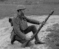
The thing there is that what he's showing in the video, is not an AFV smoke grenade discharger :) If you compare the pictures he shows at about 11:20 to the weapon he's actually holding, you'll see that the whole of the launcher cup is different. The reason for that is because the thing the video is about, is some kind of cut-down Lee-Enfield with a cup discharger for a Mills bomb on it. Apparently, this:

Cut-down_SMLE_discharger_drg.jpg

Which appears to be a First World War weapon.

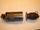
The way these work is that a No. 36 grenade (Mills bomb) was fitted with a disc that screwed into the bottom of it so that it fit well in the launch cup, and a grenade-launching cartridge¹ would then be loaded for firing it. The slot you can see in the video, with the butterfly nut on it, serves to regulate the pressure in the cup, letting the firer set the distance (approximately) to which the grenade should be launched.

But this whole thing is a lot smaller than the vehicle smoke grenade dischargers: a Mills bomb is 61 mm in diameter, the smoke grenades were 102 mm.


¹ Not a blank as Herrera is using! Americans owning these kinds of discharger cups appear to use blanks with them a lot, probably because blanks are much easier to get. But they're usually shooting things like tennis balls from them, not hand or smoke grenades, which weigh a lot more. Firing one of those using a blank might drop it dangerously close to yourself.
 
First World War weapon
...and there is this type, 1917 Enfield No.1 Mk III Lithgow "wire wrapped"

wirewrappedlithgow (2).jpg
ww1grenade (1).jpg
Holding_It (1).jpg

I came across these when reading about the LRDG.
Though it was early in my research, I may have to go back and verify that it was if fact a WW1 version in the account I read about (8 years ago).

In any case, I scratched one together, which may find a place on a vehicle someday.

17488013910275235754286412542181.jpg

... and the description of use:

1. Insert special .303 blank round that's designed for grenade launching (slow burn I believe ... see pic below) into chamber and close bolt.
2. Establish correct firing position. (see photo)
3. Start inserting special Mk36 grenade (flat bottom plug) into discharger cup until grenade lever is inside the rim of cup and being held down by cup itself.
4. Pull pin out of grenade (lever won't fly off because it's being held down inside discharger).
5. Set aim angle and pull trigger
6. Blank fires and gas expansion sends grenade down range. Note over sized grenade base called the "gas check", that helps seal gases from escaping around grenade body.

Note: Discharger actually has a sliding window like opening with a threaded lock knob (see pic), that allows gas to escape out the side in a controlled fashion. In that manner, the firer can control the amount of gas he permits to escape, so he can vary the distance grenade gets tossed. According to period grenade manual, a fully closed port will launch about 200 yards.
 
Last edited:
...and there is this type, 1917 Enfield No.1 Mk III Lithgow "wire wrapped"

View attachment 149463
View attachment 149464
View attachment 149465

I came across these when reading about the LRDG.
Though it was early in my research, I may have to go back and verify that it was if fact a WW1 version in the account I read about (8 years ago).

In any case, I scratched one together, which may find a place on a vehicle someday.

View attachment 149467

... and the description of use:

1. Insert special .303 blank round that's designed for grenade launching (slow burn I believe ... see pic below) into chamber and close bolt.
2. Establish correct firing position. (see photo)
3. Start inserting special Mk36 grenade (flat bottom plug) into discharger cup until grenade lever is inside the rim of cup and being held down by cup itself.
4. Pull pin out of grenade (lever won't fly off because it's being held down inside discharger).
5. Set aim angle and pull trigger
6. Blank fires and gas expansion sends grenade down range. Note over sized grenade base called the "gas check", that helps seal gases from escaping around grenade body.

Note: Discharger actually has a sliding window like opening with a threaded lock knob (see pic), that allows gas to escape out the side in a controlled fashion. In that manner, the firer can control the amount of gas he permits to escape, so he can vary the distance grenade gets tossed. According to period grenade manual, a fully closed port will launch about 200 yards.
i own an enfield mark IV with the same action , one of the smoothest ever built. ive shot her maybe a handful of times with 303 from an original 1000 round WW2 crate. not one hangfire.. one thing i take away from that was just how exhausting it must have been for these chaps to be firing those in anger all day every day. the rifle kicks like a mule and with the steel butt, does a number on your shoulder. it is a beast of a round for sure
 
i own an enfield mark IV with the same action , one of the smoothest ever built. ive shot her maybe a handful of times with 303 from an original 1000 round WW2 crate. not one hangfire.. one thing i take away from that was just how exhausting it must have been for these chaps to be firing those in anger all day every day. the rifle kicks like a mule and with the steel butt, does a number on your shoulder. it is a beast of a round for sure
Definitely!
Steve
 
how exhausting it must have been for these chaps to be firing those in anger all day every day. the rifle kicks like a mule and with the steel butt, does a number on your shoulder.
Long ago, I read the First World War memoirs of a German soldier. I don't remember whose, but I do recall him mentioning that after firing much of his ammunition in one of the big battles early in that war, the front of his right shoulder was one big bruise.
 
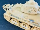
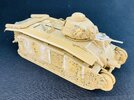
In the end, I decided to after all do my normal thing for non-workable tracks: glue them to the wheels so I can later on paint everything in a mud or dust colour, thereby avoiding the difficulty of painting all the bits in their proper colours :)

IMG_2823.jpeg
 
The H39 is pretty much finished, I'd say:

IMG_2828.jpegIMG_2832.jpeg

I added an aerial base for a No. 11 wireless set, made from a lamp from my spares box, a bit of sprue and a few punched discs, plus a bit of plastic card for a base and copper wire for the cable. I also added two fire extinguishers someone else 3D-printed for me.

IMG_2831.jpeg

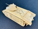
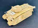
The B1 is also making progress:

IMG_2833.jpegIMG_2834.jpeg

It now has its weld seams, deliberately not too finely because it's war production with, as we say in Dutch, the French stroke ;) It also has Churchill tools, as well as a pickaxe head from some unknown other source, as I couldn't find another Churchill one. Now it needs some tow cables, an aerial base like on the H39, a couple of fire extinguishers and, I think, also the legs on which the tank could be raised from the ground (I had glued those on originally but removed them again — which reminds me that I also need to glue some plastic rod into the mountings for them).
 
Nice!

I like how your aerial base, and smoke cannister launchers with cables turned out. When painted up, they'll be quite convincing I think.

With its large body and relatively small turret, the B1 reminds me of that other famous Gaulois: ;)
download.png
 
It is a very peculiar-looking tank, yes. The French fascination with one-man turrets was very much a dead-end street, but that didn't stop them from putting one on just about everything in the 1930s.
 
A bit more tinkering with the B1 and it's now done too:

IMG_2835.jpegIMG_2836.jpeg

The tow cables are nylon string with eyelets from — again — an AFV Club Churchill. The pins that the eyes are on are plastic rod while the hooks are brass rod, all glued into holes I drilled into the armour. I first laid the cables onto the sides of the tank, trying different ways to get them to sit plausibly, and when I found those I added the pins followed by glueing on the cables themselves. Only after that did I drill the holes for the hooks. Then I added a little support for the aerial base so it lines up with the B1's normal antenna cable, and I felt that enough is enough :) I'm not going to add the legs after all, because a few of them were damaged when I removed them from the tank earlier.
 
Last edited:


Write your reply...

Latest posts

Back
Top