Medium Tank T6

Scale Model Addict - Model Tips, Guides, Tools & Tech, Tutorials, and Community

Help Support Scale Model Addict:

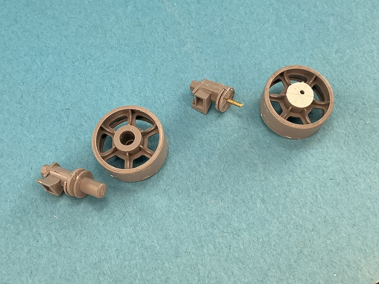
Takom's idler wheels are intended for link-and-length tracks, which have a fixed length, but I want to use separate-link track from MiniArt, and then it's better if you can use the idlers to adjust the track length:
IMG_4074.jpeg


Left as supplied in the kit, right as modified. I cut the axle off the mount by sawing through the outer disc and then filed the remains of that away. I then glued the axle into the wheel and replaced the disc by a 6 mm one punched from 0.5 mm plastic card. I then drilled a hole into the wheel, 1 mm away from the centre and also one in the centre of the mount, to take a piece of 1 mm brass rod as the new axle.

All that remained was to glue them to the hull:
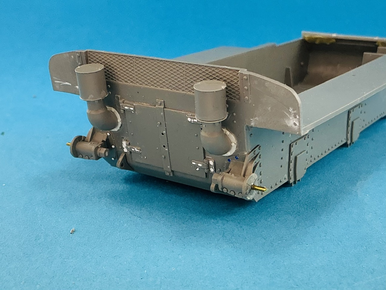
IMG_4075.jpeg


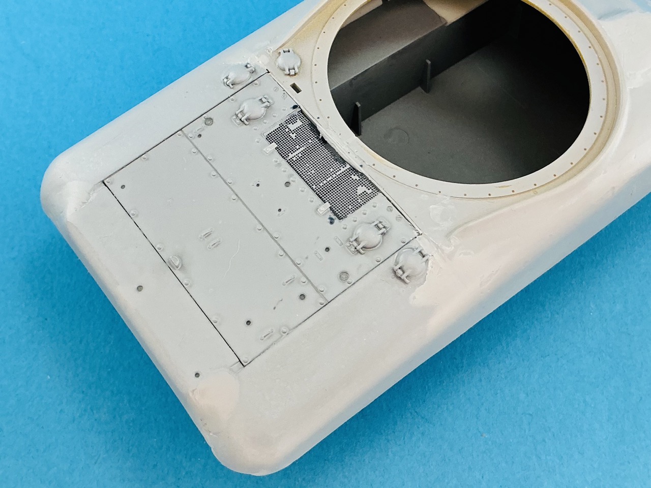
The T6's engine deck was almost the same as the M3A1's, but not quite. I first cut away the front edge of the Takom part's air intake, because it didn't fit well under the Asuka hull. I also cut away the little handwheels that were moulded inside the air intake as well as four bolt heads that were slotted screws on the T6:
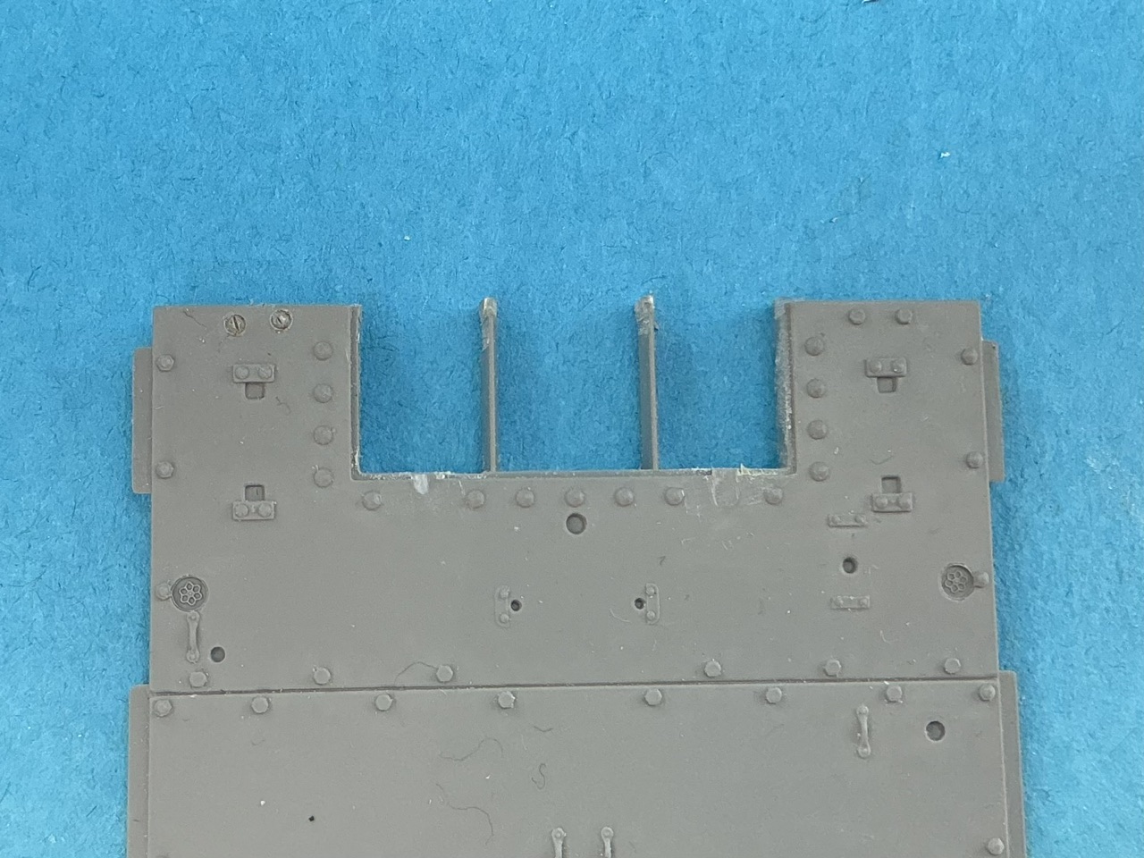
IMG_4076.jpeg


In the photo, you can see I replaced them on the left but not yet on the right, to show what I changed. I made the screws with a Trumpeter rivet-maker set. That's actually a set of metal pins with hollowed-out ends, which you can use to engrave a little circle by twisting it round, after which I used a knife to cut a line across to make the screw slot.

And in the hull:
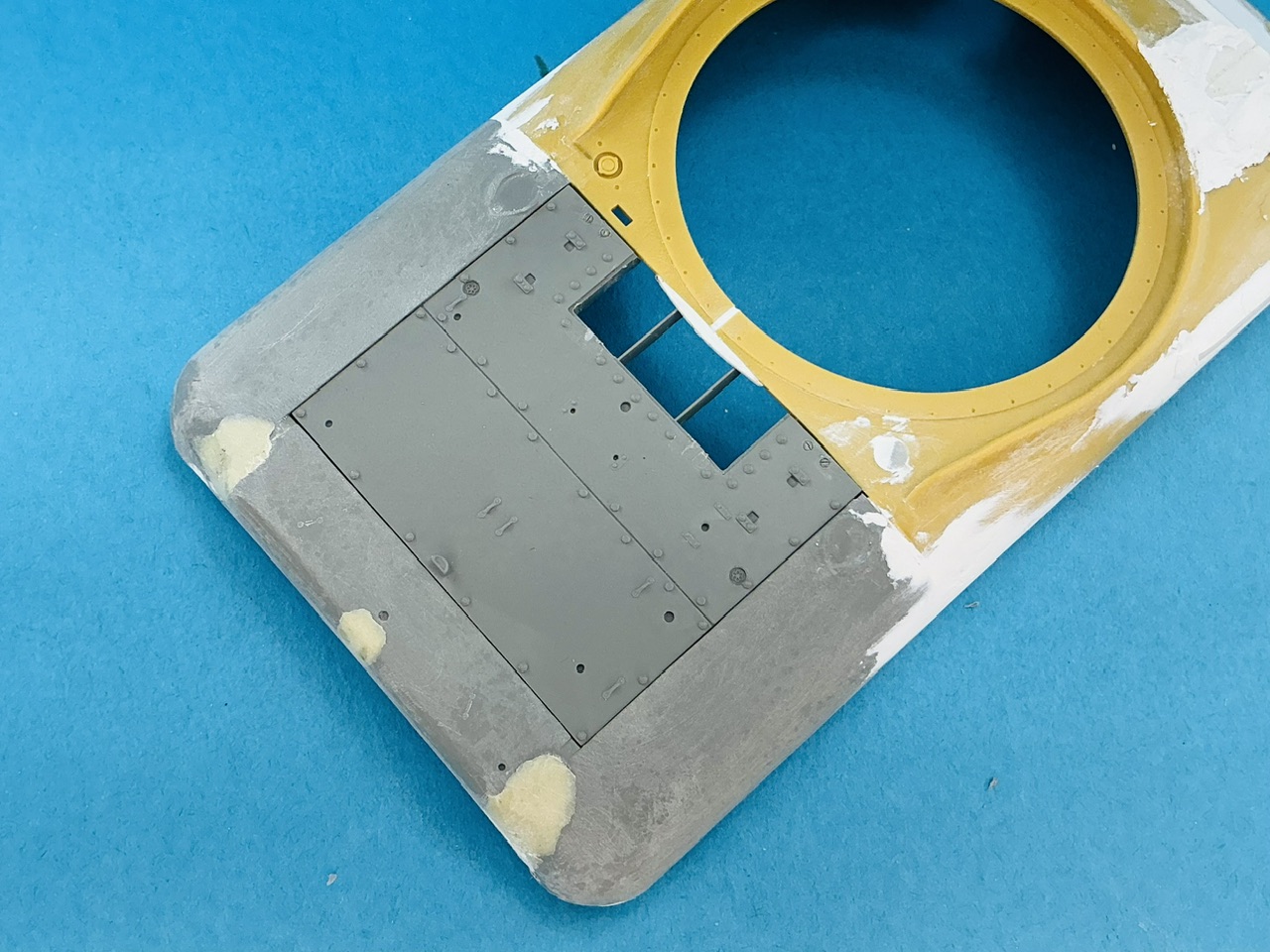
IMG_4077.jpeg


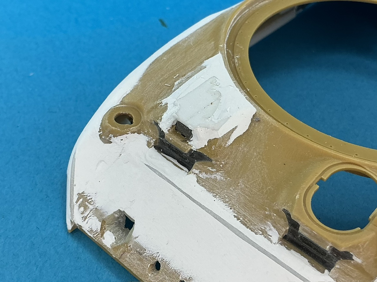
The T6 had a small, rounded section at the rear of the turret ring, which you can see in the photo above, and that I cut from 0.5 mm plastic card. There seem to be hardly any photos of the real tank that show it, because the turret is usually in the way, but it definitely was there:
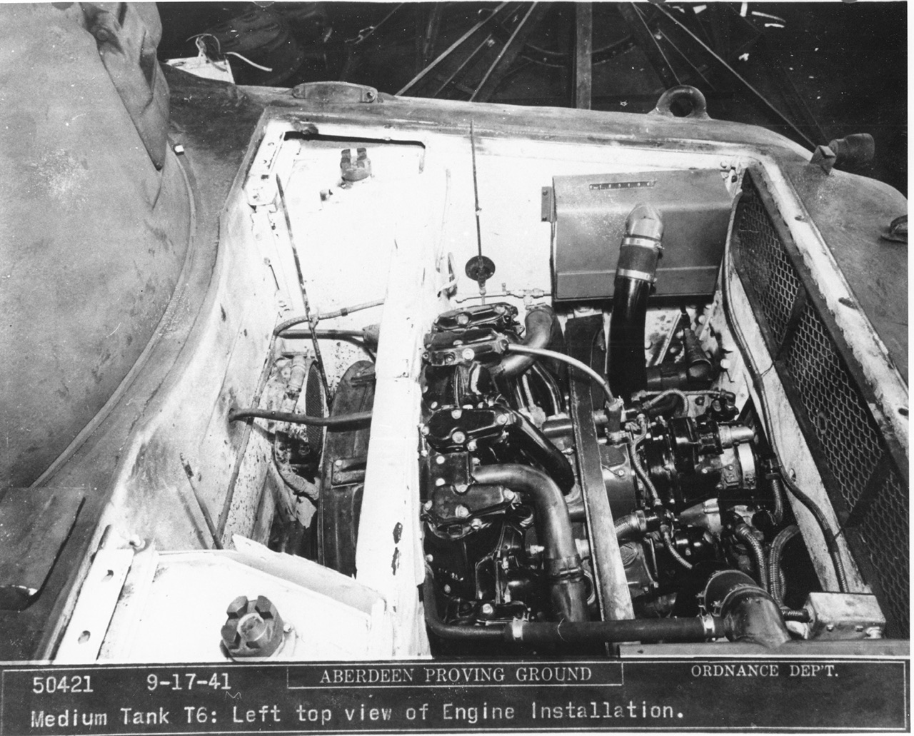
IMG_3804.jpeg
 
It's how the real thing works as well :)

Sherman idler wheel parts.jpeg


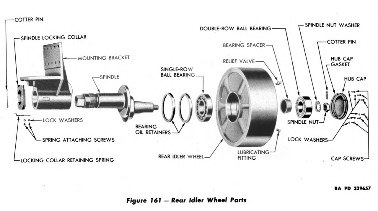
The problem with the Takom M3 kits is that the spindle has been moulded in one piece with the mounting bracket (which is shown from above in the illustration), so it's non-adjustable. Many modern Lee/Grant and Sherman kits give the bracket and spindle as separate parts, letting you adjust the track tension like on the real thing. That's what I've achieved here too with a little work. It would not have been necessary had I used Takom's tracks, but I changed the angle of the suspension to represent an unloaded vehicle, so the Takom track might be a little too short to fit correctly — and in any case, I gave away the track sprues soon after buying the kit, because I don't like link-and-length track much anyway :)
 
For now, I'm done with the putty:

IMG_4078.jpeg


I've not yet decided if the shape is correct (enough), but I'll take a closer look once I put a layer of paint over it all so it's easier to see what the shape actually is right now.

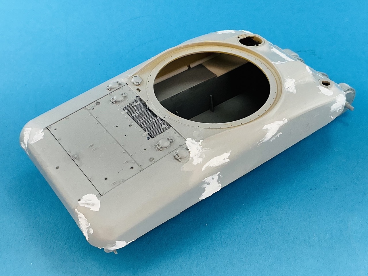
At the back, I continued working on the air intake:

IMG_4079.jpeg


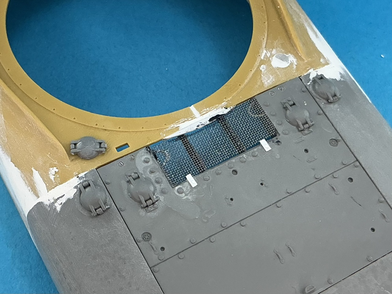
The mesh is slightly too fine (it should have two wires per millimetre, this has slightly more than that) but I had this at hand, from a broken outdoor light for tea lights or some such :) The bent pieces of strip underneath were a pain to make, that strip doesn't want to hold the curve you put into it, and that's before you even try to glue it to the model … I think I had to make five to get two in place.

The fuel filler caps are from Takom, but with the bent pins (that hold them closed) cut away, because the T6 had straight pins.
 
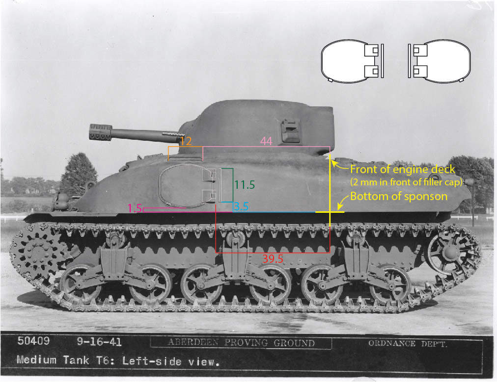
No work on the actual model since the last update, but I did do some measuring and drawing to work out the shape, size and locations of the doors:

T6 left side with door drawings and dimensions.jpg


Dimensions are for 1:35 scale. I located the door and handrail on the model by using the front edge of the left filler cap as a reference point, since this is the only fairly reliable one visible. The engine deck on my model, and hence the cut I made in the two hull parts, is 2 mm in front of that filler cap, so by drawing the yellow line there, I could locate everything else relative to the cut on the model. To anyone else crazy enough to want to build a reasonably accurate T6, I would advise doing the same :)

Interestingly, the door looks like it's symmetrical top–bottom and left–right, but it's not. The shapes of the curves in all four "corners" are slightly different, at least going by the photo.

Attached is a drawing you can save and then print out as templates to make the doors.
 

Attachments

As an Amazon Associate we earn from qualifying purchases. Product prices and availability are accurate as of the date/time indicated and are subject to change.
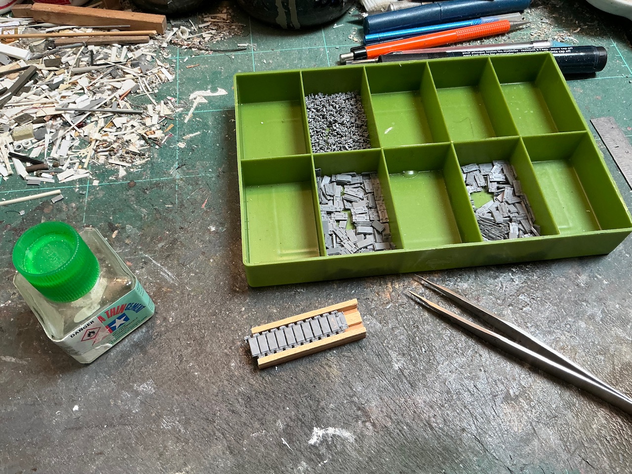
This one has been on the backburner for a bit, except that I started on the tracks last week:

IMG_4083.jpeg


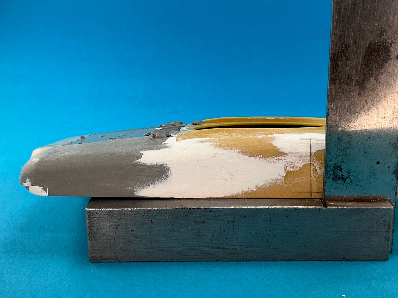
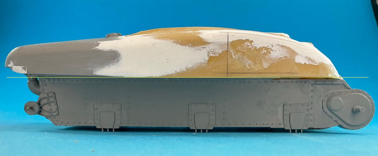
Also last week, as I was drawing the locations of the doors onto the model, I noticed something that had passed me by until then:

IMG_4093.jpeg


Or on the lower hull, with a line to make it clearer:

IMG_4094.jpeg


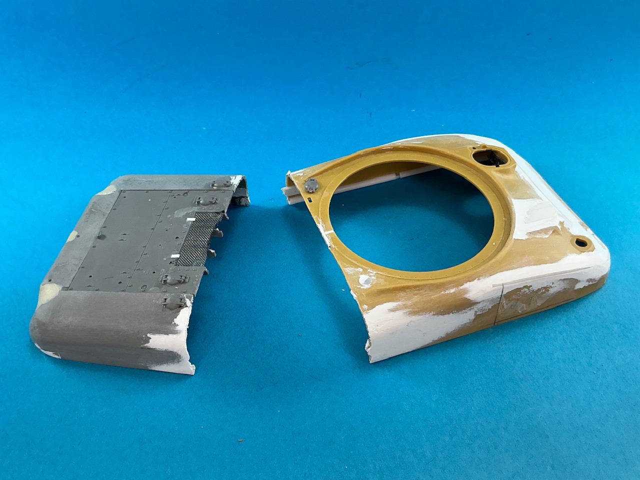
The lower edge of the upper hull shouldn't have a kink in it. Crap … Oh, well, drastic times call for drastic measures:

IMG_4095.jpeg


This time round, I'll glue the upper hull parts to the lower first, before putting the gap shut again, so I can at least ensure they line up correctly.
 
Last edited:
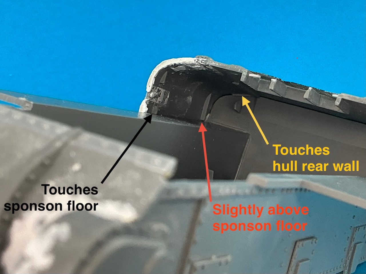
Now the two upper hull parts are loose, I could work out what the real problem was:

IMG_4097.jpeg


At the front, the locating lug rests on the sponson floor, while at the rear, the whole deck rests on the rear wall of the lower hull. But the locating lug just in front of that doesn't touch the sponson floor, even with some pressure on it. It's not that I glued the rear wall too high, though, because its lower edge sits nicely where it should in relation to the hull floor.

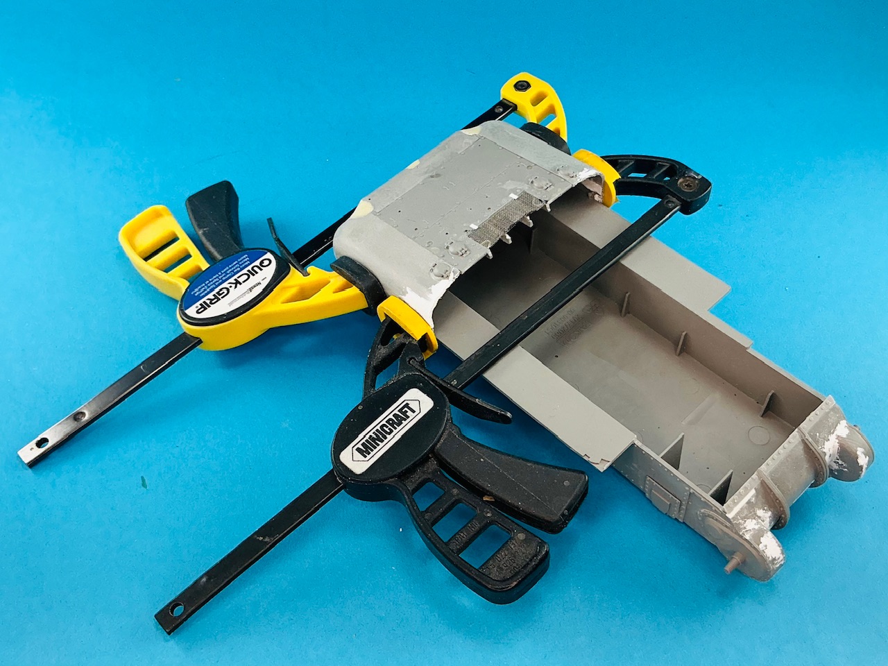
To solve this, I filed down the top of the rear wall a little and then found that the rear lug did reach the sponson floor, but only if I pressed it down lightly. Making sure the two were aligned correctly as I applied the glue, I added clamps to keep them that way until the glue dries:

IMG_4098.jpeg
 
I suppose it would not nearly be as noticeable if I had just built the M3A1 kit straight from the box. With that, even if the sponson floor doesn't quite line up with the underside of the upper hull, it would be far less visible than that kink in my grafted-together upper hull.
 
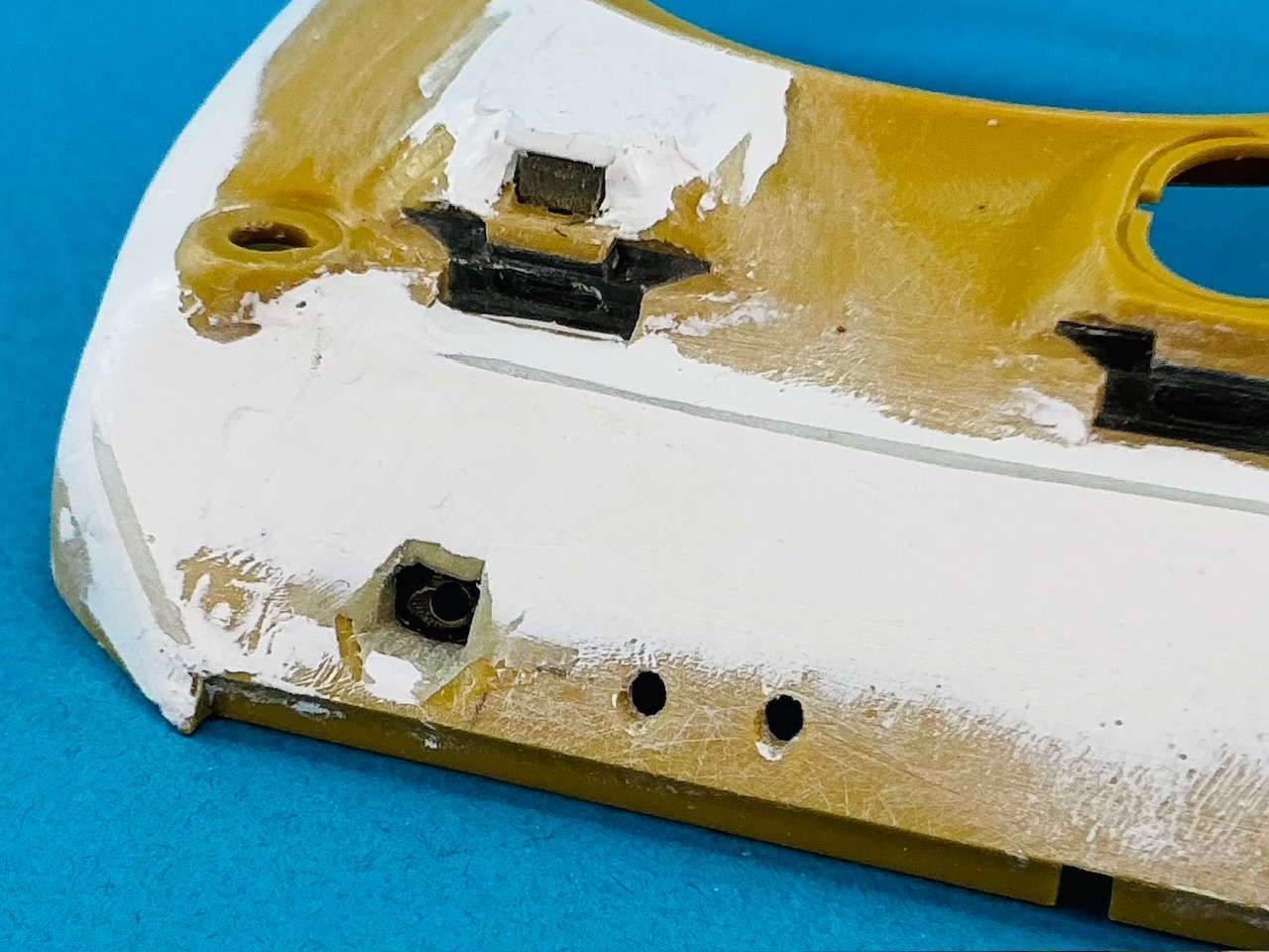
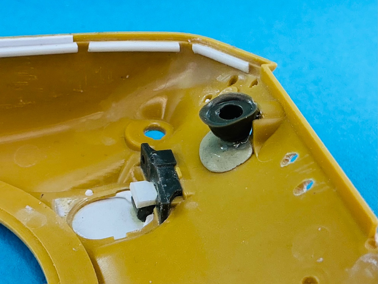
Before I could glue the hull parts together, I first had to add the mounting for the bow machine gun. On the real tank, this appears to have been a ball mount with inside it a second ball mount that the machine gun's barrel poked through; the outer ball had a slot in it to allow the gun to be aimed side-to-side. But making all of that in 1:35 is a bit much, IMHO, so I went looking for something that had approximately the right spherical shape, filed a slot in it and drilled a hole for the barrel in that slot:

IMG_4102.jpeg


But what is spherical in shape and easy to get?

IMG_4103.jpeg


An M1 helmet from Tamiya, of course! :)

I also cut pieces of plastic card to make the forward sponson floors:

IMG_4104.jpeg


These are necessary because on the T6 (and M4), this floor continues forward further than on the M3. I first glued the hull parts together and only added the floors after:

IMG_4106.jpeg
IMG_4107.jpeg


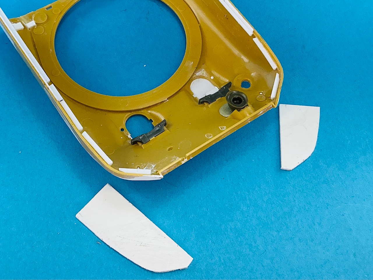
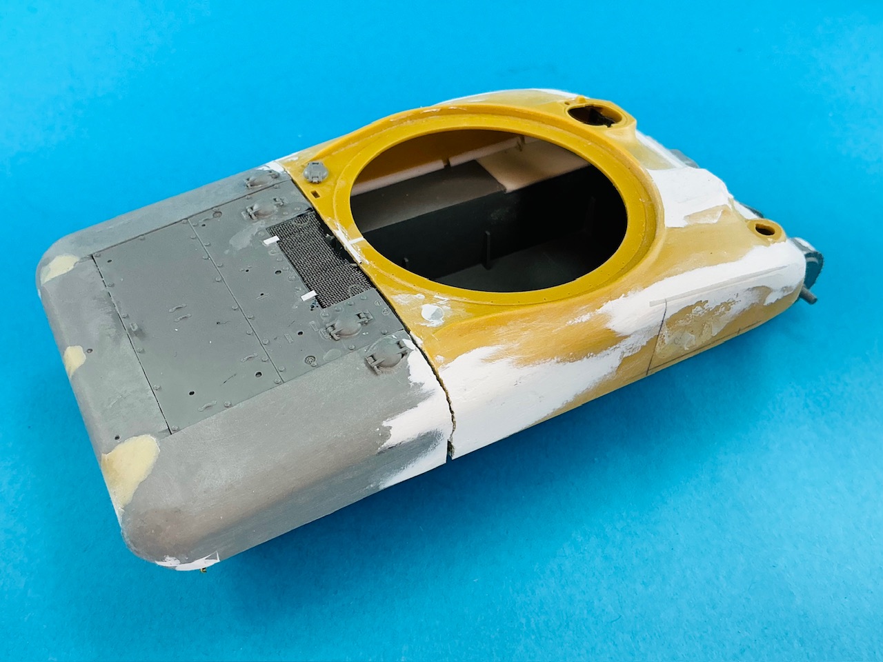
Notice the big seam between the front and rear parts. I think the rear part sits further back now than it did at first, but there's nothing to be done about that now. This is why there's some white plastic strip (0.38 mm thick) at the front, between the grey strip with bolt heads and the yellow hull. I think I'll also have to add a piece at the rear, in front of the engine deck, because the gap there is rather big too. I also need to rebuild the rounded bit of plastic there to extend the turret ring, because it broke into pieces when I took the hull apart.

Oh yeah, and before I glued the parts together, I drilled out the locating holes for the lifting eyes from the inside — it's important to not forget to do that :)

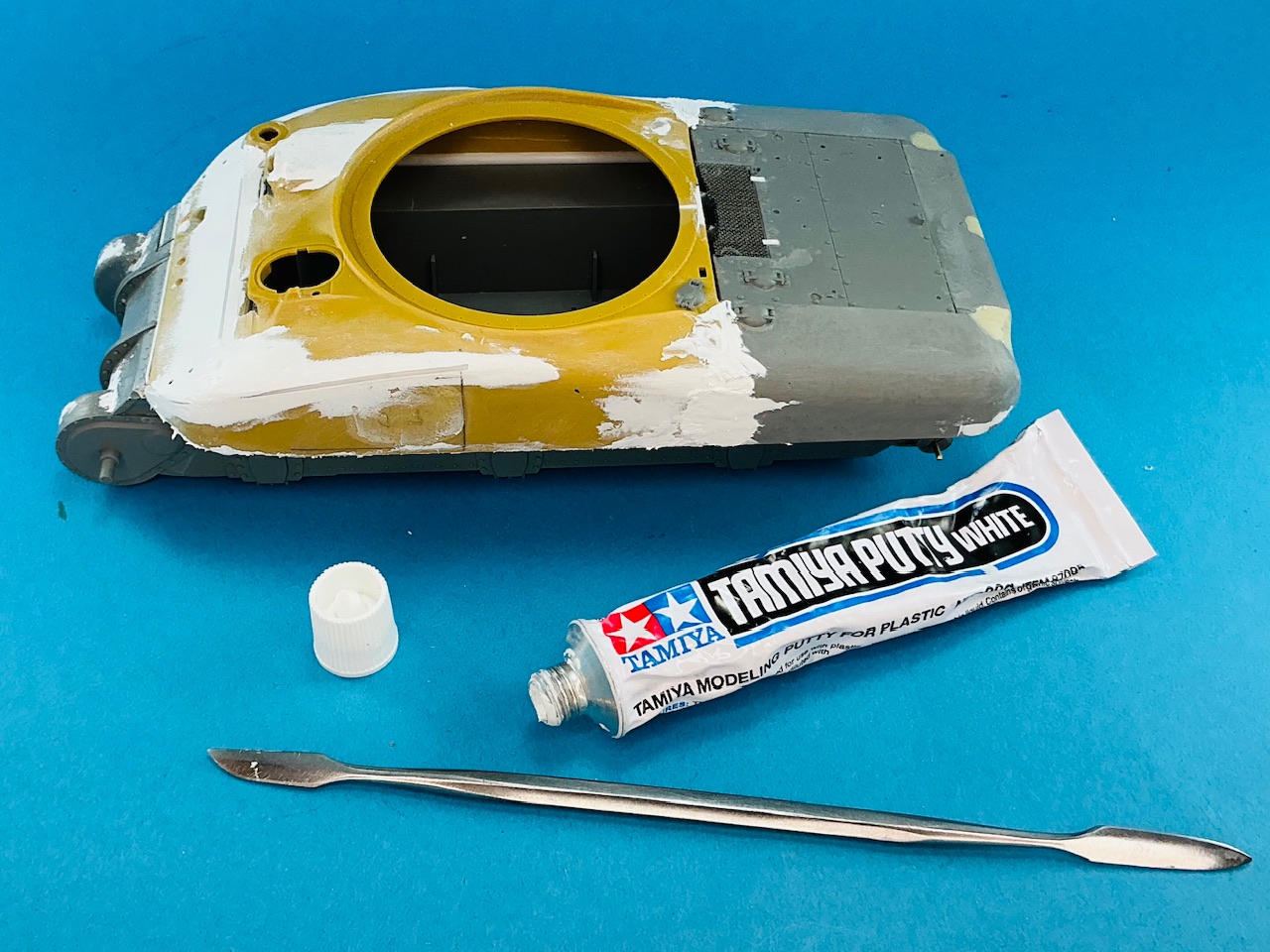
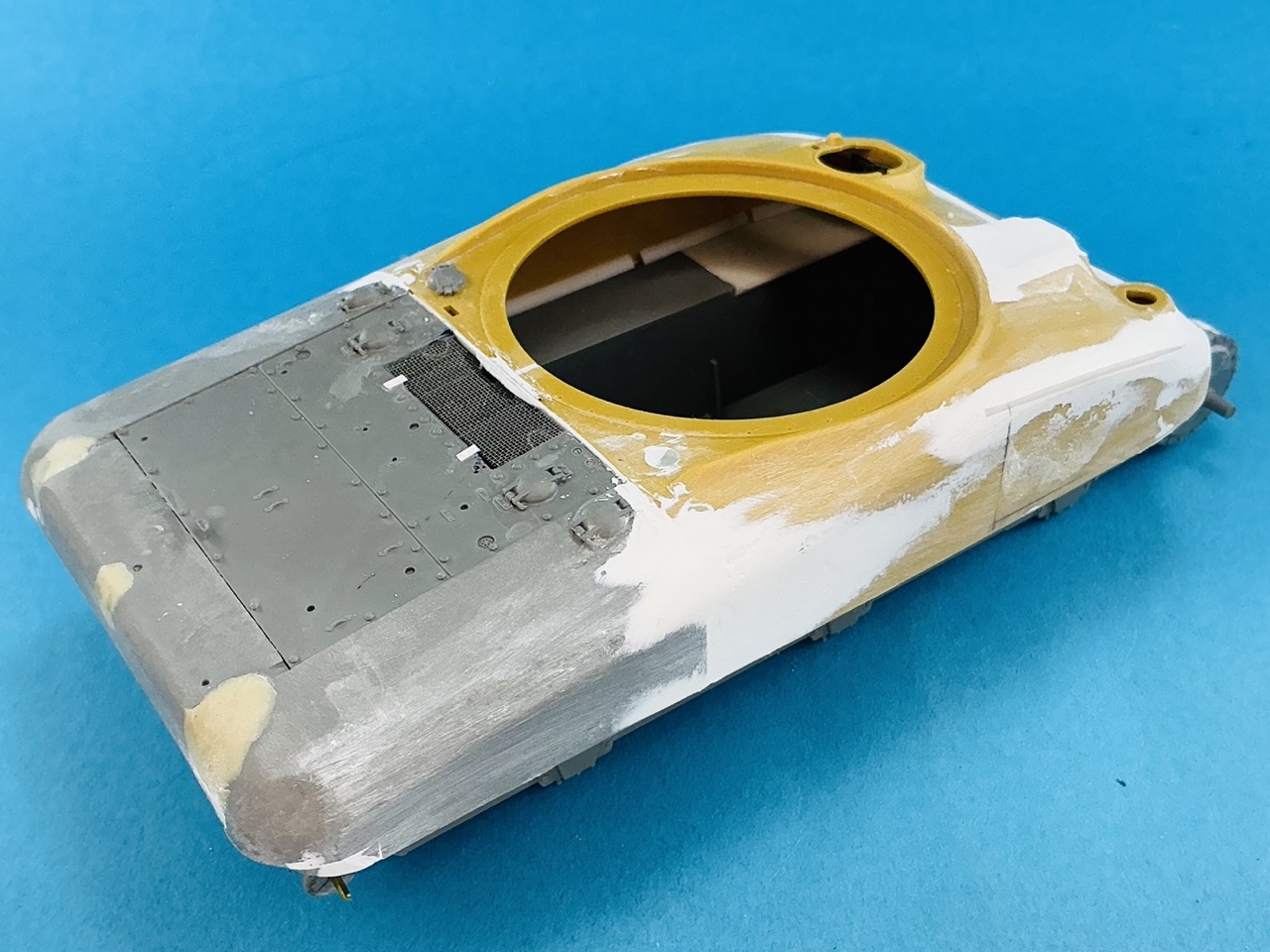
And then, naturally, out came the putty again!

IMG_4109.jpeg


I didn't just fill the gaps on the sides but also between the sponson floor plates and the hull sides, which you can just see in the picture, along the lower edge of the upper hull.

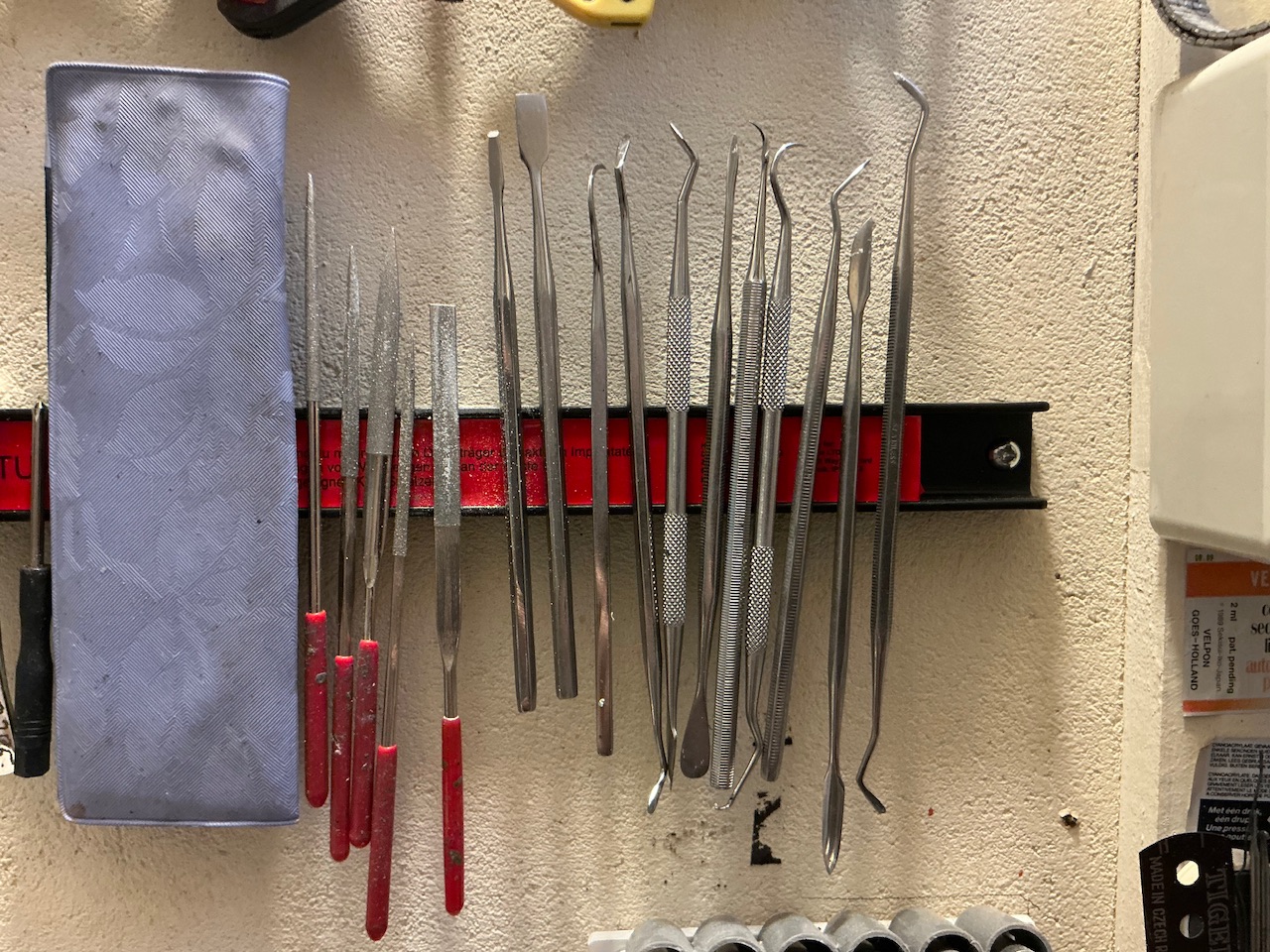
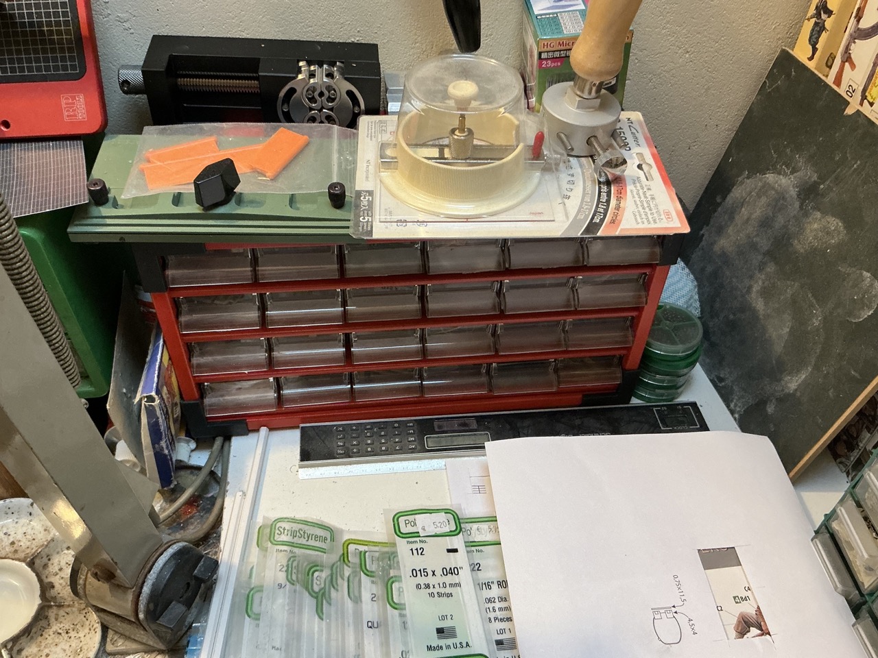
The spatula is the one I have that's most useful for this kind of work: big enough to be able to smear enough putty onto the model with, but not so big it gets in the way. Just for fun, here's a bonus picture of all the spatulas and other sculpting tools I have that I could use for this kind of work, plus some miscellaneous tools that happen to hang next to them:

IMG_4110.jpeg
 
Before I could glue the hull parts together, I first had to add the mounting for the bow machine gun. On the real tank, this appears to have been a ball mount with inside it a second ball mount that the machine gun's barrel poked through; the outer ball had a slot in it to allow the gun to be aimed side-to-side. But making all of that in 1:35 is a bit much, IMHO, so I went looking for something that had approximately the right spherical shape, filed a slot in it and drilled a hole for the barrel in that slot:

View attachment 186319

But what is spherical in shape and easy to get?

View attachment 186320

An M1 helmet from Tamiya, of course! :)

I also cut pieces of plastic card to make the forward sponson floors:

View attachment 186321

These are necessary because on the T6 (and M4), this floor continues forward further than on the M3. I first glued the hull parts together and only added the floors after:

View attachment 186322View attachment 186323

Notice the big seam between the front and rear parts. I think the rear part sits further back now than it did at first, but there's nothing to be done about that now. This is why there's some white plastic strip (0.38 mm thick) at the front, between the grey strip with bolt heads and the yellow hull. I think I'll also have to add a piece at the rear, in front of the engine deck, because the gap there is rather big too. I also need to rebuild the rounded bit of plastic there to extend the turret ring, because it broke into pieces when I took the hull apart.

Oh yeah, and before I glued the parts together, I drilled out the locating holes for the lifting eyes from the inside — it's important to not forget to do that :)

And then, naturally, out came the putty again!

View attachment 186324

I didn't just fill the gaps on the sides but also between the sponson floor plates and the hull sides, which you can just see in the picture, along the lower edge of the upper hull.

The spatula is the one I have that's most useful for this kind of work: big enough to be able to smear enough putty onto the model with, but not so big it gets in the way. Just for fun, here's a bonus picture of all the spatulas and other sculpting tools I have that I could use for this kind of work, plus some miscellaneous tools that happen to hang next to them:

View attachment 186325
Love the use of the helmet! That's good thinking!
 
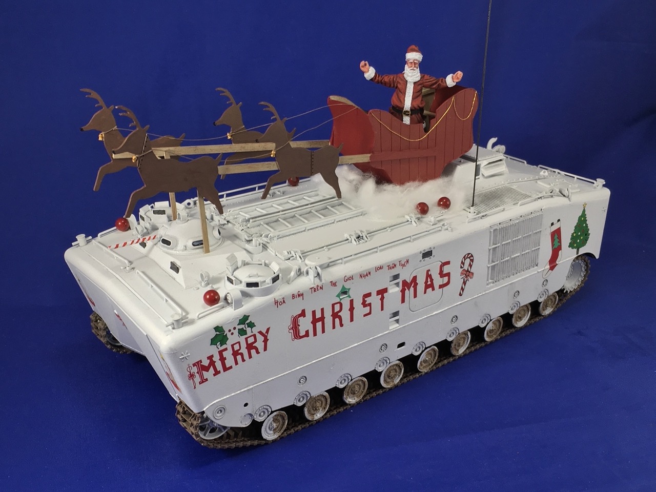
My first idea was that I have some yellow airsoft pellets somewhere, but I don't recall where — I last used (and saw) them about seven years ago to make the red baubles on this model:

IMG_5003.jpeg


The next idea was to go looking through my spare parts, and one of those helmets looked about the right size. So, problem solved :)
 
the place where you have "enough" spare parts?
LOL, such a place exists?!🤔

A few seasons ago, while pruning branches, the extension pole trimmer fell apart... No worries, I know I have something in the basement: sure enough, to the surprise of everyone (except my wife who's seen it all before), I emerged a few minutes later with exactly the right locknut, still sporting the 'Raleigh' bicycle logo from a bike I had as a teenager a billion years ago!
 
Do you ever get to the place where you have "enough" spare parts?
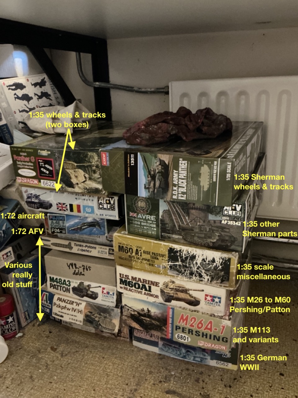
Eh … I'll let you be the judge of that … Here's my boxes with most of my spare parts:

IMG_4121.jpeg


Pretty much all of this is leftover bits from kits, plus a small number of accessory sets I stored with them. Some parts are on the sprues, usually if there were a lot from a single kit (like near-complete sprues left over) but a great many of them are loose. None of them started out as boxes this big, except the very well-worn one for the 1:35 miscellaneous parts, third from the top on the right. That one was my only spares box initially, but when it became too small I put the wheels and tracks into the Scimitar box (second from the top on the left). Eventually I had to separate the parts by subject to be able to find anything again. Some also were originally in smaller boxes and then moved to bigger ones when they started overflowing.

For the Sherman parts, a few years ago I then sorted nearly all of them into ziplock bags and boxes because it was getting unworkable to find the bits I needed. So, for example, there's a bag with Sherman mudguards, one with main guns, one with hatches, one with engine decks, a box with separate compartments holding spoked wheels, stamped wheels, dished wheels, and so on … (The reason for the vast amount of Sherman spares is partly because I built quite a lot of them in recent years, and partly because nearly all modern Sherman kits come with a literal handful of leftover parts.)

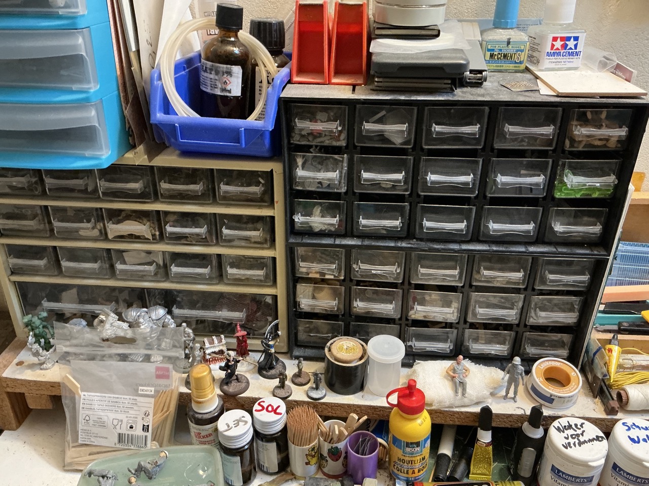
And then I have these for the smaller bits:

IMG_4122.jpeg
IMG_4123.jpeg


In the first photo, the brown chest of mini-drawers is all assorted ancient stuff dating back 30+ years. The black one has mainly F/SF wargaming stuff in the top half and 1:35 infantry equipment and general stowage in the lower half. In the second photo, the drawers have assorted vehicle parts (one with smoke launchers, one with radios, one with periscopes, one with headlamps, and so on).

And this is not including the boxes of figures and more general accessories that are still on their sprues, rather than removed from them for putting in those drawers.

Right, on to the T6 again ;)


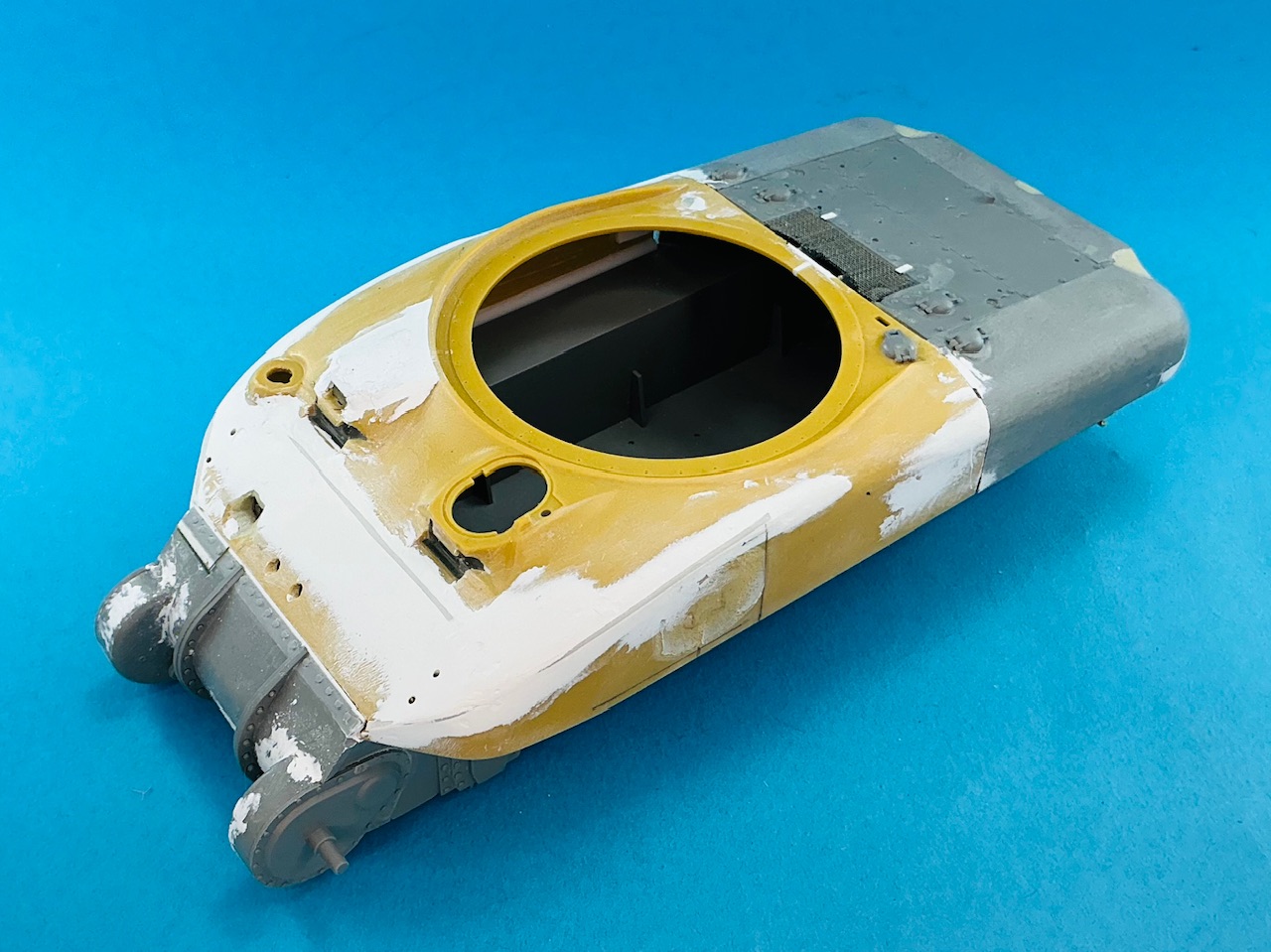
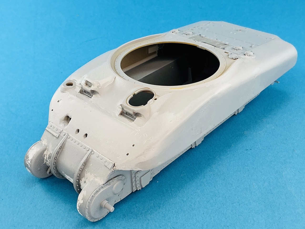
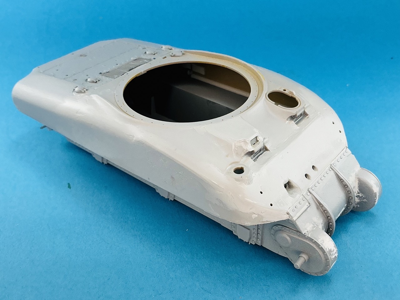
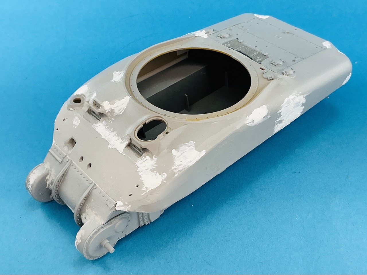
Now that I sanded the putty, I'm pretty much where I was again before I broke the upper hull in two:

IMG_4119.jpeg


I also added a bit of plastic strip and a rounded section to the front of the engine deck.

Now I think I'll need to spray some primer into much of this to see how much work it still needs before it's actually done.[/hr]
 
Eh … I'll let you be the judge of that … Here's my boxes with most of my spare parts:

View attachment 186453

Pretty much all of this is leftover bits from kits, plus a small number of accessory sets I stored with them. Some parts are on the sprues, usually if there were a lot from a single kit (like near-complete sprues left over) but a great many of them are loose. None of them started out as boxes this big, except the very well-worn one for the 1:35 miscellaneous parts, third from the top on the right. That one was my only spares box initially, but when it became too small I put the wheels and tracks into the Scimitar box (second from the top on the left). Eventually I had to separate the parts by subject to be able to find anything again. Some also were originally in smaller boxes and then moved to bigger ones when they started overflowing.

For the Sherman parts, a few years ago I then sorted nearly all of them into ziplock bags and boxes because it was getting unworkable to find the bits I needed. So, for example, there's a bag with Sherman mudguards, one with main guns, one with hatches, one with engine decks, a box with separate compartments holding spoked wheels, stamped wheels, dished wheels, and so on … (The reason for the vast amount of Sherman spares is partly because I built quite a lot of them in recent years, and partly because nearly all modern Sherman kits come with a literal handful of leftover parts.)

And then I have these for the smaller bits:

View attachment 186451View attachment 186452

In the first photo, the brown chest of mini-drawers is all assorted ancient stuff dating back 30+ years. The black one has mainly F/SF wargaming stuff in the top half and 1:35 infantry equipment and general stowage in the lower half. In the second photo, the drawers have assorted vehicle parts (one with smoke launchers, one with radios, one with periscopes, one with headlamps, and so on).

And this is not including the boxes of figures and more general accessories that are still on their sprues, rather than removed from them for putting in those drawers.

Right, on to the T6 again ;)


Now that I sanded the putty, I'm pretty much where I was again before I broke the upper hull in two:

View attachment 186449

I also added a bit of plastic strip and a rounded section to the front of the engine deck.

Now I think I'll need to spray some primer into much of this to see how much work it still needs before it's actually done.[/hr]
Well if you ever need a lost part …
 
I'm happy to donate spares to other people, especially ones I have several of. But only if it's not going to break the bank in terms of postage :)
 
It wasn't a quick decision :) I spent a few days thinking about it on and off before I decided it would make the model better (and not look like I took the easy way out :) ).
 

Latest posts

Back
Top