Battlewagon: M4A3E8 ETO
- Thread starter errains
- Start date
panzerace007
New Member
- Joined
- Dec 17, 2010
- Messages
- 2,118
Texaslobo said:Thanks for the data panzerace007, Will have to get some.
LOBO - Just to clarify - When the Matte Medium Gel is used to attach a model to it's base - Do Not Thin . Just use it straight, that also goes for when you mix Paint, washes or pigments with it to make Mud.
errains
New Member
- Joined
- Apr 10, 2011
- Messages
- 288
Part 5-Making Tracks
Link-to-link tracks for many people are without question the most intimidating part of the building process, myself included. The key here is being patient and having a good plan of attack. The decision was made to assemble the tracks so that they can be removed, painted and weathered and then attached, with hopefully only minor touchups, to the suspension components. T66 tracks are a single track link connected with a pin that makes them somewhat easier to assemble then the other VVSS type tracks that use end connectors.
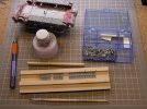
A simple jig was constructed from basswood to assist in the assembly of the track. The track was built in groups of five links and then attached to form the long bottom and top runs. For the drive sprockets and idler wheels, groups of four to five links are assembled and attached to the respective sprocket/idler. The track runs from the first and last road wheels to the sprockets/idlers, which are made of five to seven links. Once the glue had dried a bit but is still pliable, the lengths were test fitted…lots of test fitting will be required to get it right.
Even with test fitting there was still a gap at the end of the run. Narrowing a link, with a little carving and filing, the gap was filled and hopefully not too noticeable.
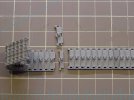
The dark links are from an earlier generation Dragon M4A3E8 kit. Additional links for storage on the upper hull are needed, so with a little extra filing and proper placement on the kit, the substituted links will not even be seen.
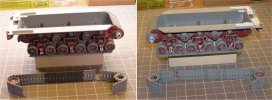
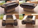
Thanks to for all kool comments and suggestions thus far from the HERD. The house is nearly unpacked and I may actually get back to working on this puppy this weekend ;D
Link-to-link tracks for many people are without question the most intimidating part of the building process, myself included. The key here is being patient and having a good plan of attack. The decision was made to assemble the tracks so that they can be removed, painted and weathered and then attached, with hopefully only minor touchups, to the suspension components. T66 tracks are a single track link connected with a pin that makes them somewhat easier to assemble then the other VVSS type tracks that use end connectors.
A simple jig was constructed from basswood to assist in the assembly of the track. The track was built in groups of five links and then attached to form the long bottom and top runs. For the drive sprockets and idler wheels, groups of four to five links are assembled and attached to the respective sprocket/idler. The track runs from the first and last road wheels to the sprockets/idlers, which are made of five to seven links. Once the glue had dried a bit but is still pliable, the lengths were test fitted…lots of test fitting will be required to get it right.

Even with test fitting there was still a gap at the end of the run. Narrowing a link, with a little carving and filing, the gap was filled and hopefully not too noticeable.

The dark links are from an earlier generation Dragon M4A3E8 kit. Additional links for storage on the upper hull are needed, so with a little extra filing and proper placement on the kit, the substituted links will not even be seen.


Thanks to for all kool comments and suggestions thus far from the HERD. The house is nearly unpacked and I may actually get back to working on this puppy this weekend ;D
errains
New Member
- Joined
- Apr 10, 2011
- Messages
- 288
noname said:I went to have a quick look at some Shermans and it seems there isn't much for slack in the tracks. Perhaps I'm wrong. I'd still throw a little in for good measure.
NoName,
Thanks for the suggestion. Like you I also did some digging through my reference photos just to make sure I didn't miss something. I believe as a general rule Sherman’s kept their tracks a bit on the tight side as compared to say the Russians. The only sag I noticed was vary slight between the Idler and last return roller. See the below pix for a sample of T66 tracks.
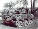
Since mine are already assembled I’ll keep them as is for this build. However I may include this small sag. It would be nice if Sherman’s had more sag, as it would provide some visual interest.
Once more thanks.
BTW: Does anyone know what the items circled in red are? To me they look like VVSS EECs. If so then the question would be ‘Why is an HVSS Sherman carrying VVSS EECs?’ Might make for an interesting storage item…hmmm
Jeep
Member
- Joined
- May 8, 2010
- Messages
- 400
It is hard to see the red area clearly, but several of my sherman tank references mentioned that M4E6 and M4E8 were often fitted with "duckbill" end connectors and ice cleats, even with the HVSS suspensions wider tracks, the extra plating added to the standard sherman hull plus the extra thickness in the transmission cover and mantle castings added a LOT of extra weight, the extended end connectors were apparently a fairly common addition. However, other sources have also stated that the were also fairly fragile so it would make sense to me that the crew may hold lengths of track extensions ready but not installed. I'll try to figure out where I read about the above information, its on my shelves some where.
noname
New Member
- Joined
- Jun 16, 2010
- Messages
- 1,487
I never noticed before how tight the tracks were on these things. It just looks really odd to me. But if that is the way it was then you should go with it. I wonder if they ever got any sag after x amount of use? You'd think they'd stretch a tad after a while. Maybe this system had some sort of tensioner?
S
ScaleModelMadman
Guest
When it comes to Sherman tracks, it's not only about being correctly tensioned but the fact that they are 'live' tracks and not 'dead' tracks makes a huge difference. Both live and dead tracks have the ability to set/adjust tension but the tension alone isn't what causes the Sherman tracks to remain so rigid.
The Tiger/Panther/PnzrIV etc. all use 'dead' track, which is essentially just slabs of steel attached to one another via a pin in a chain like fashion, the weight will cause the track to sag a little in between the return rollers, when this track is laid on flat ground, it will lie flat.
Shermans and other allied vehicles use 'live' track, which differs greatly as there is a bushing which puts tension on the connection at the track pin. This linked, chain like assembly becomes slightly more complex, as that bushing causes the track to bend slightly inward. A length of live track left on the ground will curl upward slightly at each end or perhaps begin to roll itself up a little. When installed, the track itself tends to bend inward and in turn upward, slightly assisting the sprocket and conforming to the wheels somewhat but also keeping the length of track in between the return idlers flat.
If you look at most photos of Sherman tanks, there should be no, or in some cases very little sag. Looking at photos of blown/brewed up Shermans will often show track sag as the bushings are destroyed in the fire allow them to behave more like dead tracks.
*
As far as those links on the front of that 14AD tank, they may be carried only as protection/extra armor and not necessarily as spare track, so they could be just about anything really, even German track length if that happens to be the case.
They aren't 'duckbill' end connectors as those are merely small extensions that attach to each individual link and wouldn't be able to be hung there in that fashion without being attached to the accompanying track length. Same goes for ice cleats, which are merely small bars that attach on the face of the track and varying intervals.
Duckbills in the top attachment
Ice cleats in the bottom attachment
[attachment deleted by admin]
errains
New Member
- Joined
- Apr 10, 2011
- Messages
- 288
Part:6 Just a Few Details
Let me start by first saying thanks to Ken for laying down some useful insights on the difference between Live and Dead tracks....THANKS Man!!
First up is Welding;
Using liquid cement, lay down the weld using .020†evergreen styrene rod, .015†might be better for scale effect. Once the rod had softened a bit, then form it around the curved areas and allow to dry about 24 hours. When bending the rod around curved areas, you may have to use a fast drying cement such as Ambroid Pro Weld.
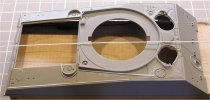
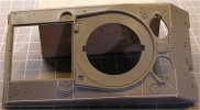
After the styrene rod had dried, dice/chop it along the various lengths. After that tedious process, divide the weld areas into workable sections. Applying liquid cement and let it sit for about 7 to 10 minutes to get it nice and soft. Then dice/chop the soft weld. The idea here is to add additional cuts to replicate weld beads and to somewhat flatten the rod.
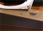
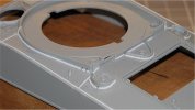
A few suggestions, if you feel like trying this method, please practice on an old spare kit first. Also make sure you have very good lighting and if needed a good set of magnifying glasses to help see what you are doing. Always use a new sharp knife blade when doing the dicing/chopping. Not necessarily a new method, but it’s the one that gives me the best results.
Next is the Lifting Rings;
The lifting rings supplied in the kit are satisfactory but look a bit anemic. I decided to replace them with a suitable size wire. After a quick search around the work area an acceptable product was located, 14gage lead-free silver solder. To determine the correct diameter of the bend for the rings the original kit parts served as guide. Select a round object that fits inside the ring to serve as a form, a grill bit works well. Next cut a length of wire, solder or whatever you are using. Ensuring that wire/solder is straight, bend it around the form as shown in the photo.
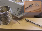
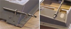
Using the gluing davits as a guide drill the appropriate size holes through the plastic. Insert the newly made rings into the holes. Use the form to set the height of the rings as shown below and super glue into place from the inside of the hull.
For the welds, epoxy putty can be used. Roll the putty into a thin thread and wrap around the base of the lifting ring. Using a suitable flat tipped object such as an old #11 hobby knife blade, the back side not the sharp side, texture the putty into a wield pattern.
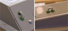
I think welds turned out ok but maybe a bit over sized and a bit too course. An additional suggestion would be once the epoxy thread is in place let it sit for a time and harden a bit before applying the weld texture. As usual practice this a couple of times before doing this to your current build.
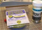
Below are the two products that where used to make the lifting rings.
Lastly are Grab Handles;
I’ll be covering the constructing of handles for hatches, power plant access doors and this can even be use for tie downs.
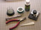
The Jig below helps form the handles into the basic shape. The best part of this jig is that it’s free with the only cost being in materials used to build it. I built this one about 15 years ago!!
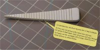
Another option for forming the handles is to use a PE folder if you own one already. Just use an appropriate sized “finger†on the folder to set the width of the handle and finish squiring it off with your handy pliers.
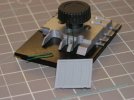
The following illustration steps you through the process of using the jig to form the shape of handle, not hard to do but does need a little practice.
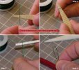
Next is to attach the handles to the location. Use a spacer to help set the height of handle. On the backside bend the wire in to help hold the handle in place. Use whatever glue you like and allow to dry.
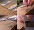
That’s it your handles are basically done. If you like add a little epoxy putty for welds at the base of the handles.
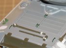
I hope many of you found these helpful and provide ideas that you can apply to your future modeling projects and if anyone has additional insights related to these or other techniques please shair with the rest of us!!
Let me start by first saying thanks to Ken for laying down some useful insights on the difference between Live and Dead tracks....THANKS Man!!
First up is Welding;
Using liquid cement, lay down the weld using .020†evergreen styrene rod, .015†might be better for scale effect. Once the rod had softened a bit, then form it around the curved areas and allow to dry about 24 hours. When bending the rod around curved areas, you may have to use a fast drying cement such as Ambroid Pro Weld.


After the styrene rod had dried, dice/chop it along the various lengths. After that tedious process, divide the weld areas into workable sections. Applying liquid cement and let it sit for about 7 to 10 minutes to get it nice and soft. Then dice/chop the soft weld. The idea here is to add additional cuts to replicate weld beads and to somewhat flatten the rod.


A few suggestions, if you feel like trying this method, please practice on an old spare kit first. Also make sure you have very good lighting and if needed a good set of magnifying glasses to help see what you are doing. Always use a new sharp knife blade when doing the dicing/chopping. Not necessarily a new method, but it’s the one that gives me the best results.
Next is the Lifting Rings;
The lifting rings supplied in the kit are satisfactory but look a bit anemic. I decided to replace them with a suitable size wire. After a quick search around the work area an acceptable product was located, 14gage lead-free silver solder. To determine the correct diameter of the bend for the rings the original kit parts served as guide. Select a round object that fits inside the ring to serve as a form, a grill bit works well. Next cut a length of wire, solder or whatever you are using. Ensuring that wire/solder is straight, bend it around the form as shown in the photo.

Using the gluing davits as a guide drill the appropriate size holes through the plastic. Insert the newly made rings into the holes. Use the form to set the height of the rings as shown below and super glue into place from the inside of the hull.

For the welds, epoxy putty can be used. Roll the putty into a thin thread and wrap around the base of the lifting ring. Using a suitable flat tipped object such as an old #11 hobby knife blade, the back side not the sharp side, texture the putty into a wield pattern.

I think welds turned out ok but maybe a bit over sized and a bit too course. An additional suggestion would be once the epoxy thread is in place let it sit for a time and harden a bit before applying the weld texture. As usual practice this a couple of times before doing this to your current build.
Below are the two products that where used to make the lifting rings.

Lastly are Grab Handles;
I’ll be covering the constructing of handles for hatches, power plant access doors and this can even be use for tie downs.

The Jig below helps form the handles into the basic shape. The best part of this jig is that it’s free with the only cost being in materials used to build it. I built this one about 15 years ago!!

Another option for forming the handles is to use a PE folder if you own one already. Just use an appropriate sized “finger†on the folder to set the width of the handle and finish squiring it off with your handy pliers.

The following illustration steps you through the process of using the jig to form the shape of handle, not hard to do but does need a little practice.

Next is to attach the handles to the location. Use a spacer to help set the height of handle. On the backside bend the wire in to help hold the handle in place. Use whatever glue you like and allow to dry.

That’s it your handles are basically done. If you like add a little epoxy putty for welds at the base of the handles.

I hope many of you found these helpful and provide ideas that you can apply to your future modeling projects and if anyone has additional insights related to these or other techniques please shair with the rest of us!!
panzerace007
New Member
- Joined
- Dec 17, 2010
- Messages
- 2,118
ERIC,
Fantastic Stuff !! Great SBS ! Great Idea on th handle maker !! She's lookin' Sharp !!
Fantastic Stuff !! Great SBS ! Great Idea on th handle maker !! She's lookin' Sharp !!
scratchmod
New Member
- Joined
- Feb 13, 2011
- Messages
- 856
Some very nice work going into this build- and nice toot's to boot.
scratchmod
scratchmod
errains
New Member
- Joined
- Apr 10, 2011
- Messages
- 288
Part:7 Gun Tubes and Sandbags
Greetings everyone!
Last week I attended the monthly meeting of the Central Virginia chapter of AMPS in Richman Va. It was an awesome environment for sharing ideas and techniques. I wish to thank all the members of the chapter for making me feel welcomed. Additionally I would like to Thank Erick & Frank, whom are members of the herd, for the invite.
In this installment the RB Models 76mm main gun tube with muzzle break and 30cal MGs additionally a layer of supplemental armor will be added to the build to the lower hull.
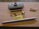
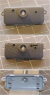
First step was to rework the mantlet using a Dremel engraving cutting bit to give it a cast texture.
The engraving bit is lightly passed over the plastic in a random pattern. This produces a heavy texture, which is more at home on Russian type castings. I always wanted to try this and am happy with the result, but not really appropriate for American castings. However this same method has been used on the transmission cover and will be also used on the turret to maintain consistency throughout the subject. Next I replaced the lifting rings with plastic rod that was thermoformed around an appropriate sized drill bit and submerged into boiling water. Small diameter plastic tube was use for the 30cal coaxial…not really happy with the way it turned out. Finally the foundry marking are of course from Archer 3D casting symbols.
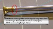
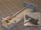
Once the muzzle break was assembled the gun tube was then attached to the mantlet using a simple jig. Plastic strips run through the muzzle break help insure that it is square with the mantlet.
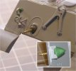
Lastly the bow mounted 30cal MG was assembled and placed into the hull. Epoxy putty was used to secure it from the inside.
Next up is Patton’s Aggravation
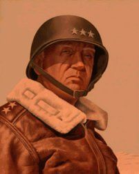
As has been well documented Gen. Patton had, shall we say had definite opinions regarding the use of supplemental armor, notably sandbags. Despite his efforts to discourage the practice tankers had other ideas. The supplemental armor arrangements used by tanker during World War II makes modeling this era one of the major enjoyments. And finally I got to the point where it was time to add on the sandbags, oh the fun. However at the sometime I realized that if not properly done it could also severely distract from the over all finish. With excitement and apprehension I proceed with caution. The entire process took three weeks not wanting to rush the results.
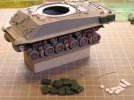
Used spacers, the white blocks, so that the jerry can would sit at the edge of the fenders.
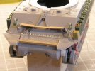
The wood planking to support the sandbags. The wire as shown in the inspirational photo to secure the sandbags.
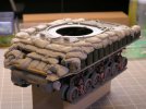
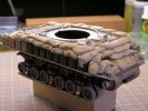
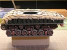
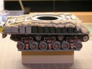
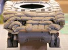
I feel the results are satisfactory and capture the essence of the photograph. If anything the sandbags are bit on the large size. I used http://www.magicsculp.com/ ] Magic Sculp [/url] a two-part epoxy putty that I picked up on ebay for the making the sandbags. Let me know what you think.
With this posting the building progress is up to date and I have started working on this again after my recent move into a new house. I'll be posting a new update here soon on external stowage. .
See you all then!
Greetings everyone!
Last week I attended the monthly meeting of the Central Virginia chapter of AMPS in Richman Va. It was an awesome environment for sharing ideas and techniques. I wish to thank all the members of the chapter for making me feel welcomed. Additionally I would like to Thank Erick & Frank, whom are members of the herd, for the invite.
In this installment the RB Models 76mm main gun tube with muzzle break and 30cal MGs additionally a layer of supplemental armor will be added to the build to the lower hull.

First step was to rework the mantlet using a Dremel engraving cutting bit to give it a cast texture.
The engraving bit is lightly passed over the plastic in a random pattern. This produces a heavy texture, which is more at home on Russian type castings. I always wanted to try this and am happy with the result, but not really appropriate for American castings. However this same method has been used on the transmission cover and will be also used on the turret to maintain consistency throughout the subject. Next I replaced the lifting rings with plastic rod that was thermoformed around an appropriate sized drill bit and submerged into boiling water. Small diameter plastic tube was use for the 30cal coaxial…not really happy with the way it turned out. Finally the foundry marking are of course from Archer 3D casting symbols.


Once the muzzle break was assembled the gun tube was then attached to the mantlet using a simple jig. Plastic strips run through the muzzle break help insure that it is square with the mantlet.

Lastly the bow mounted 30cal MG was assembled and placed into the hull. Epoxy putty was used to secure it from the inside.

Next up is Patton’s Aggravation

As has been well documented Gen. Patton had, shall we say had definite opinions regarding the use of supplemental armor, notably sandbags. Despite his efforts to discourage the practice tankers had other ideas. The supplemental armor arrangements used by tanker during World War II makes modeling this era one of the major enjoyments. And finally I got to the point where it was time to add on the sandbags, oh the fun. However at the sometime I realized that if not properly done it could also severely distract from the over all finish. With excitement and apprehension I proceed with caution. The entire process took three weeks not wanting to rush the results.

Used spacers, the white blocks, so that the jerry can would sit at the edge of the fenders.

The wood planking to support the sandbags. The wire as shown in the inspirational photo to secure the sandbags.


I feel the results are satisfactory and capture the essence of the photograph. If anything the sandbags are bit on the large size. I used http://www.magicsculp.com/ ] Magic Sculp [/url] a two-part epoxy putty that I picked up on ebay for the making the sandbags. Let me know what you think.
With this posting the building progress is up to date and I have started working on this again after my recent move into a new house. I'll be posting a new update here soon on external stowage. .
See you all then!
Similar threads
- Replies
- 18
- Views
- 2K
