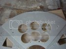
AMT/MPC Falcon rebuild

Yes it is, I dont know what kit brand it was from though. its 1/76 scale so it is almost the right size. It and a few other pieces are going to be very handy.

Thanks for looking

Ozzy
 
This was one of the best looking mpc builds that I'd ever seen, I'm sure your revamped version will look fantastic. Keeping an eye on this one!
 
Going all out on this again hey ????

8)

I wish I had your courage ! and Dedication !

Keep up the good work !

Norm

OUT !
 
Hi guys, just a quick update.

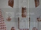
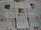
Been working on the engine deck. Have had some problems with some pieces along the side walls so moved over to the engine deck.

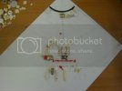
DSC00239.jpg

Only the wheel is finalised, the rest I am still working on, or am going to change. I will be making the Panther tank rear just a shade smaller.

Thanks for looking

Ozzy
 
Hello Ozzy!

Are you using this styrene sheet for placement purpose Only? or are you gluing those parts down on it now?

The reason I am asking is..... That rear section of the falcon "as you know"! Is somewhat Convex.....

If you try to glue that large sheet down on your saucer section Subframes (Ribs). You might experience 'some' of those parts POPPING OFF! Or Maybe not?

It seems that you have been collecting Greebies for quite some time!

Keep up the good work!

Norm.
 
Hi norm,

Thats a good question. I have been debating if to make a new engine deck (as I plan for it to be removable like the 5 foot for access to wiring) or sand down the original. Both aint easy!!

I havnt actualy been collecting greebles other than 2-3 pieces from a sherman tank kit and the red parts you see are from an old AMT 1/20th car kit that I have been cutting and pasting together. The rest are from made from styrene (white) two part apoxy (dark grey-green, the same as I use for my 1/6th head sculpts and castings (yellow-white) of multiple pits and pieces I have glued together to make a basic shape to work with. The Tank deck is styrene, and cast vents cut down from a larger engine deck, the rest of it is made up of offcuts from casting including the hinges.

The F1 wheel was the hardest to construct. The base is the lower section of the plastic wheels you can see in top right and left (there for size placement only) and a top made from styrene and a press stud. This was cast for the basic shape and four spokes and the further cut and shaped to the final wheel.

The Hurricane wing section is just styrene scribed. I found a paper model I used as a template.

The strut "thingees" that fan out at the end of the engine deck are exact casts of another model, no modification there. Well a little modification as they are 2 seperate parts.

Thats why its taking soooo long, as I dont have any pieces that are just pull off the sprue and glue. Some are still very ruff as well, and need finner detail added. I am just trying to get the shape and size right first then I will add some extra detail, if I can.

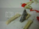
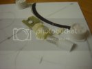
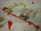
Here is a closer look, you can see they still need some work.

DSC00246.jpg
DSC00244.jpg
DSC00243.jpg

If you have a suggestion on the engine deck replacement Norm I would appreciate the help. Would you replace it or sand down the old one?

Thanks ozzy
 
I'm not Norm but I'd sand down the old one. Then all you have to do is cut along the straight edges and build in a couple of strips on the underside of the hull for the deck to rest on. You'd also have the option of not having to sand down the entire thing, whereas if you built it totally from scratch you'd have to re-create EVERY greeblie, even the ones that are correct.
 
Thanks scott, hows yours going?

Hi Ziz, unfortunate nothing on the old MPC engine deck are correct. Total sand or nothing. But the old one does already have the curve in it, and I wouldnt have to make the fins again.

Tks

Ozzy
 
I don't understand why you would want to pop the lid on the Falcon in a place like the Engine deck? Where all the attention is FOCUSED!

I know you John! A bit anyway! and you like your Projects! How ever Involved they might be? So I won't discourage you from doing it! Your way!

You must have your reasons! If its for accessing wires and such! So be it!

Sanding the Rear section of the AMT Falcon sounds a little drastic! In my eyes! But if you are after
A TRUE representation of the Filming miniatures Greebies .... Then? You might not have a choice!

Building a new "Virgin" saucer section and then adding all the bits and pieces might be the only way to satisfy your quest for accuracy? But you might find it hard to do if you do it on a flat surface?

I know you I'll come up with something! You always do!

Do you have the Star Wars books? Which shows the building of the Large falcon model? Maybe you could get some inspiration fom that? If you don't? I might be able to help!
 
I have a few pics of the building of the falcon, but only one or two that show the actual construction. If you have something that you could share that would be great. I have had some trouble working out how the attach the side walls as well. I mean I can just attach them to the outside top and bottom, but if I kit this in any way for others to use then it needs to be constructed in a way it can be attached easily.

Thank for your input buddy.

Ozzy
 
If you're thinking in terms of kitting the parts, take a step back and look at it from that perspective. Break down the design of what you're making vs what part of the original kit is staying and focus on the interface between the two.

What will the builder need to do to modify their kit to use your parts? Ideally you want to keep this to a minimum. Where they do have to hack into their kit, either make it very simple or provide a template they can use to trace out the shape they need to cut.

How will the parts fit and align together, either two of your own parts or a kit part and your part? Get square and rectangular strip - Evergreen or Plastruct, whichever is easier to find where you are - and start experimenting with making things like gluing tabs, support braces and slots for other parts and tabs to fit into.

It doesn't matter how much effort you put into the design and details if the parts don't fit on the kit easily in the first place.
 
Thanks Ziz, I have seen your kits and parts, and I know you know what you are talking about, so I appreciate your advice.

Ozzy
 
Just getting caught up, nice so far and the conversation between you and Ziz was informative!
 
Hello,

Prety much cut and past from TRF thread, its a bit too big to do over agaon, hope you dont mind.

I am still struggleing with some of the parts for the front madable walls and the engine deck, so no updates till i get something I am not embarrassed the show. I am hopeing to be less crap at it in the near future.

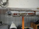
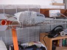
In the meantime I have hacked away at the body of the falcon to see if the new measurments I am comming up with (based on the parts I am making that are used muliple times around the ship) to see if it looks right.

First of all I cut the parts that would be most affected by the "hambergering" of the body. The docking ring halls, and the cockpit tuble.
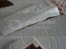
DSC00260.jpg
DSC00259.jpg
DSC00250.jpg
DSC00252.jpg

Then I cut off the fin section at rear (I will be replacing with new ones) and the lower front landing bay (which is tooooo shallow), and the engine exausts on the engine deck. I had planed to reuse these, but I am going to make some new one with actual moving mini electric fans inside them ( ya ya I know dream on LOL.)
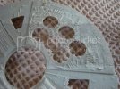
DSC00256.jpg
DSC00257.jpg
DSC00262.jpg

this is the correct size for the tank deck. Landing bay box to be sized around it.
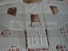
DSC00263.jpg

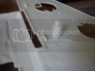
Next sanded down the engine deck.

DSC00263.jpg

Undecided as to whether to do the drop on engine deck, removable or just greable this. Anyone been here before have an opinion?

Ok next I put in the burger spacer and some electrical conduit for attaching the falcon in different possitions. I used 20mm2 heavy duty conduit so I can put what ever I can find as the side/bottom attachments. I dont have a clear solution yet.
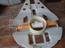
DSC00271.jpg

I only attached it to the bottom for the moment so I can figure out what wiring is going into it.

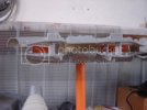
Next (after24 hours waiting for the apoxy to dry) I lowered the height of the spacers around the body to mach my new side wall height of 1.6cm. This is an increase of 1 cm from my original falcon. Ohh and the spacer is 5cm. The spacer is also a change and represents the docking ring size (which I have estimated) matching the walkways being level (does that make sence?)
DSC00269.jpg

OK, fitting top and bottom. With the cockpit as well to see how it looks against the side wall height.
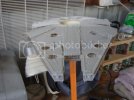
DSC00274.jpg
DSC00273.jpg
DSC00275.jpg
DSC00276.jpg
Well thats it, even though I have made estimates to try and ensure I get the right sizes for the falcon to be a good representation of the 5 foot falcon, I am also relying on phot reference to see that it has the same look against my own photo's. Not science I know, but the ultimate end result for me is a falcon that "looks" like the 5 foot.

Ohh forgot, I shortened the rails that run top and bottom of the inner mandables as well, but forgot to take a pic

Thaks for looking

Ozzy
 
Nice work on this. I now know what work would be required to get mine to look correct. WOW!
 
Thanks Grendels,

I noticed I posted a pic twice. The second one should have been the engine deck sanded.

DSC00267.jpg

Tried to get back in and edit it, but couldnt for some reason. Anyway will need to fill those holes, and make smaller ones.

TKS

Ozzy
 

Latest posts

Back
Top