1/35 RFM Easy Eight (#5028)

Scale Model Addict - Model Tips, Guides, Tools & Tech, Tutorials, and Community

Help Support Scale Model Addict:

Edbert

Well-Known Member
Joined
May 16, 2024
Messages
3,121
Pretty much all of you know I am not really an "armor guy" but I think tanks are really cool. Since starting up the hobby again last year I have built 4 tanks, all made by Meng, and one of them was the just for fun cartoon version.
  • M3-A3 Bradley
  • Merkava Mk.V
  • Panther Ausf D
  • King Tiger (the toon version)
I did start working on a Stuart from AFV club, but found the fit to be a struggle and have set it aside many times. So, wanting a break from Meng and probably not buying another kit from AFV anytime soon I bought this Sherman from Rye Field Models. I broke bags on it long ago to check out the tracks, found the individual links on the Merkava and Bradley to be very good, the Panther had me gluing strips of track together and I did not even try, I went with the white-metal ones from Fruil. So I was very interested in the way RFM did individual links. Once I got it figured out and assembled a few inched I put the kit away for another day.

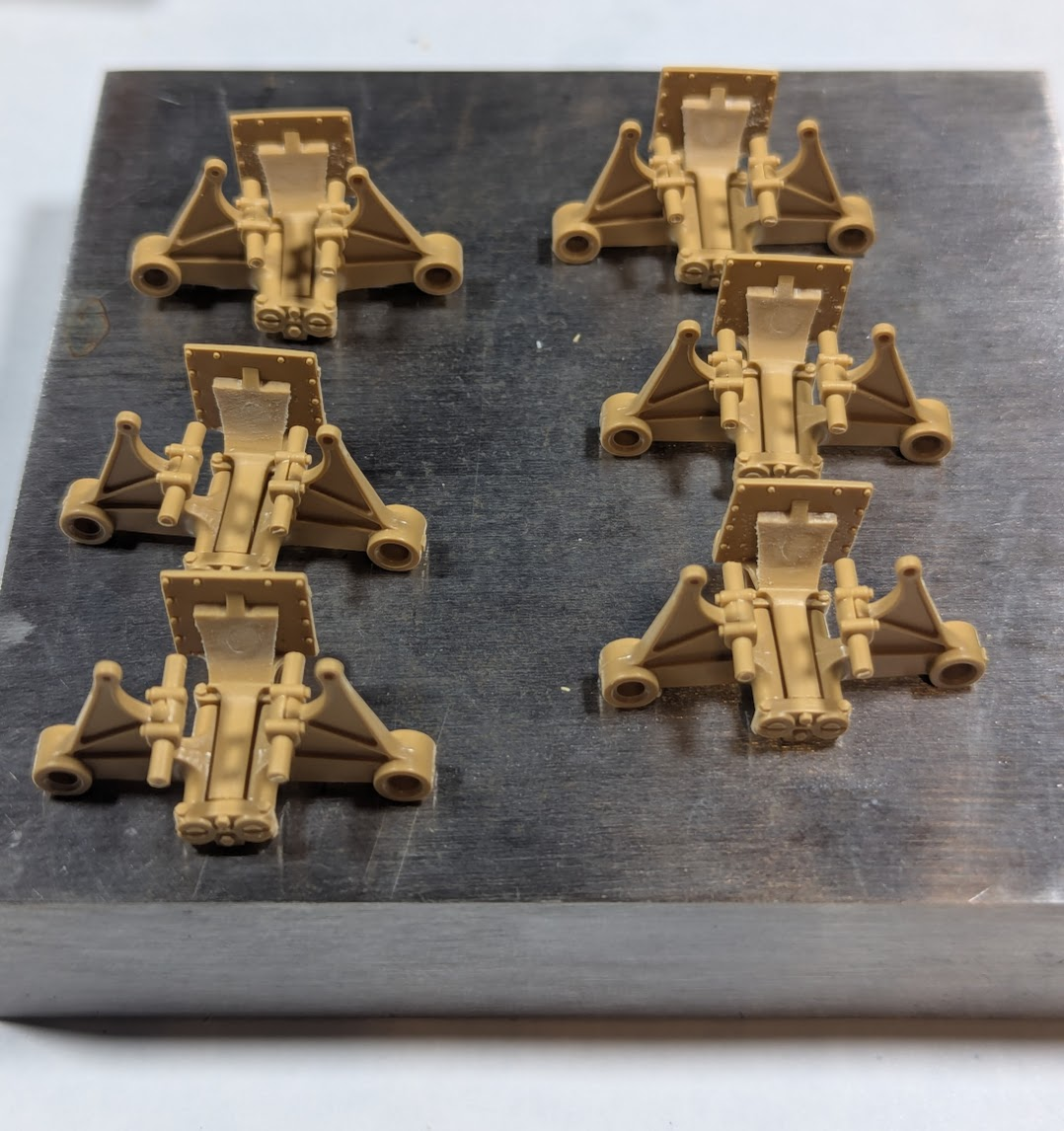
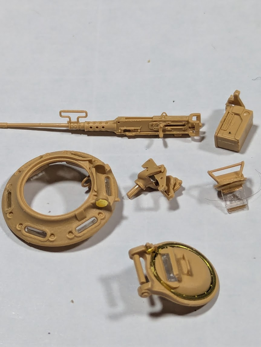
That day was this weekend, now pretty much over. This might be the most complicated assmbly on a tank I've yet encountered. So far nothing that doesn't fit or work, and the instructions are EXCELLENT. But the number of parts involved on something like a hatch, or the Ma Duece is definitly high and contains intricate bits. To wit...
1759717698545.png


This picture of those sub-assemblies is 43 parts, not kidding! So progress is going to be slow here, and as I usually do I'll take frequent breaks and work on other stuff for a while. But I will keep going n this and finish it this fall.

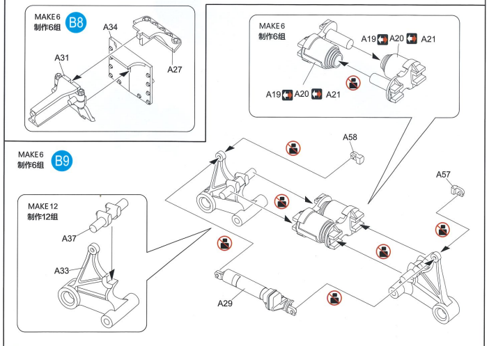
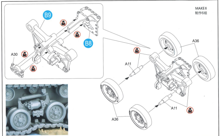
I did find something hard to figure out with the instructions, hoping someone here can help. There are six bogie (right term?) assemblies per side, each one is made of 13 parts each not including wheels, and the instructions show that no glue is to be used. I'm wondering if that is a mistake. I can pretty much put an assembly together just in my hands, but without glue they fall apart when I try to just set them down. What?!?
1759718303656.png

1759718274926.png

Forget B8 & B9, I know those steps involve glue, but the rest say not to. It seems to me that A29, A57 and A58 need to be glued. You can see that B8 sub-assembly needs to be CAREFULLY glues to A30, I got that done, but what is going to hold the three A's together?
 
Those look like very nicely engineered parts at 1:35!
Is it possible, if even executable, that A57 somehow glues to A29, neither being glued to A33(as per the diagram), fixing A29 in position but still allowing movement of the wheel pairs (if one pair goes up, the other goes down), either side of the B8 assembly?
 
Pretty much all of you know I am not really an "armor guy" but I think tanks are really cool. Since starting up the hobby again last year I have built 4 tanks, all made by Meng, and one of them was the just for fun cartoon version.
  • M3-A3 Bradley
  • Merkava Mk.V
  • Panther Ausf D
  • King Tiger (the toon version)
I did start working on a Stuart from AFV club, but found the fit to be a struggle and have set it aside many times. So, wanting a break from Meng and probably not buying another kit from AFV anytime soon I bought this Sherman from Rye Field Models. I broke bags on it long ago to check out the tracks, found the individual links on the Merkava and Bradley to be very good, the Panther had me gluing strips of track together and I did not even try, I went with the white-metal ones from Fruil. So I was very interested in the way RFM did individual links. Once I got it figured out and assembled a few inched I put the kit away for another day.

That day was this weekend, now pretty much over. This might be the most complicated assmbly on a tank I've yet encountered. So far nothing that doesn't fit or work, and the instructions are EXCELLENT. But the number of parts involved on something like a hatch, or the Ma Duece is definitly high and contains intricate bits. To wit...

View attachment 165142

This picture of those sub-assemblies is 43 parts, not kidding! So progress is going to be slow here, and as I usually do I'll take frequent breaks and work on other stuff for a while. But I will keep going n this and finish it this fall.

I did find something hard to figure out with the instructions, hoping someone here can help. There are six bogie (right term?) assemblies per side, each one is made of 13 parts each not including wheels, and the instructions show that no glue is to be used. I'm wondering if that is a mistake. I can pretty much put an assembly together just in my hands, but without glue they fall apart when I try to just set them down. What?!?

View attachment 165147
View attachment 165146
Forget B8 & B9, I know those steps involve glue, but the rest say not to. It seems to me that A29, A57 and A58 need to be glued. You can see that B8 sub-assembly needs to be CAREFULLY glues to A30, I got that done, but what is going to hold the three A's together?
Think you are off to a great start.Nicely done.
Richard
 
I can pretty much put an assembly together just in my hands, but without glue they fall apart when I try to just set them down. What?!?
What you need to glue are parts A57 and A58 to shock absorber A29, and end plate A30 to the assembly from step B8. This way, two suspension arms will be hinged to the "base" part that later glues to the tank, and the shock absorber will connect their tops. You need to make sure that A57 and A58 are tight against the top of the suspension arm without getting any glue between them. If you don't, the shock absorber may slip off the suspension arm, so press them together well and then leave them be until the glue sets.

Going by the drawings, all of these are pretty much straight copies of Asuka's HVSS parts (I wonder if they're interchangeable? the axles won't be, by the looks of them, but maybe the rest is), and that makes me think that the best way to assemble this is not how the instructions tell you to. Rather, add the suspension arms to assembly B8 by trapping them with A30 and only then add the springs A19/20/21 and the shock absorber A29/57/58.

BTW, you can glue the bogies to the hull before you add the wheels, meaning you can leave those off until after painting. By glueing the axles A11 to half of the wheels, that will let you put a wheel without an axle behind the bogie (so between the hull and a suspension arm), then push a wheel with axle onto it from the outside.

Also, if you don't want a working suspension, the best way to assemble the kit is to have it working anyway. After you glue the bogies to the hull and that glue has dried, set the hull on a flat surface (a piece of glass is ideal), push and pull the suspension until everything is level, and flow liquid cement into all of the joints. Again, leave it be until the glue sets :)
 
What you need to glue are parts A57 and A58 to shock absorber A29, and end plate A30 to the assembly from step B8.
I did glue the B8 assembly to A30, had to be careful but it worked well, the control arms all swing free.

1759756407283.png

It does seem like A57 and A58 for sure need to be glued despite what instructions say, but what holds A29 in place? There's two tiny pins. If I put any glue on A29 I lose the movement.

You're right about leaving the springs out for a bit (see photo) and you're also right about adding wheels later, after painting. That will be super easy to accomplish. One thing I do like about building wehicles is the ability to skip around the instructions.

I'll go ahead and put A57/A58 in place and wait a while on A29. Might try reaching out to RFM for some clarity here.
 
....aaaaannnnddd...I just figured it out. Amazing what a good night's sleep and strong coffee will do!

1759757320760.png

Shown above are two of the shocks and a few of the A58s (A57 is slightly different so I've learned the hard way to not cut both off the sprue at once, do all the 58s THEN snip the 57s), you can see there's a tiny notch in the back of the shock where it mounts to the arm. The base of A58 fits into there. You can see it is in place on one shock and not the other, just held in with gravity in the photo. It is going to be a challenge to glue the 57/58s to the shock without gluing the shock to the control arms, particularly when attaching the other end since then I'll be holding the springs in with my extra fingers. But I like doing this stuff, remember to tell myself that whenever it gets frustrating, LOL.

Man these are small parts. I'm going to have to withdraw my opinion that aircraft in general have smaller bits tighter details than armor :cool:
 
As an Amazon Associate we earn from qualifying purchases. Product prices and availability are accurate as of the date/time indicated and are subject to change.
It does seem like A57 and A58 for sure need to be glued despite what instructions say, but what holds A29 in place?
A57 and A58 do. The way to fix the shock absorber, at least on the Asuka version and so almost certainly here as well, is to put the pin on A29 through the hole at the top of a suspension arm, then glue A57 or A58 to A29 and press it firmly in place (easily done between thumb and index finger). This will let the shock absorber pivot on the suspension arm, and because it can do that on both sides, the whole suspension is workable.

You do need to be very careful with the glue, though: a small drop of Tamiya extra thin on the flat on A57 or A58 will do.

You're right about leaving the springs out for a bit (see photo)
You must fit those before you add the shock absorber. There's no way to get them in afterward.

And that's why I mentioned that it's much easier to add the suspension arms to the hull bracket first. If you do it like RFM (and Asuka) suggests, you have two arms that are connected only by the fairly weak hinges on the shock absorber, but must somehow manoeuver and hold the springs between them and stick both onto the bracket. But if you put them on the bracket first, like you have done, all of it's much more solid, making it far easier to put in the springs. For one thing, they won't drop out as easily due to gravity.

One thing I do like about building wehicles is the ability to skip around the instructions.
I've mentioned it before, but I generally regard the instructions as a guide for where to put the parts, not as the order in which they should be glued together :) There are exceptions, but that's a matter of keeping your eyes open to spot those.
 
I'll be in on this one Ed. Looks like you're off to a great start on this.

Strong coffee always seems to help.
oge32q.gif
 
Last edited:
Did some more work on this guy. I've settled into a pattern where I have 5 or more kits in-progress at a time. Pull one out after a bit, do some work, sometimes a lot sometimes a little, then put it away again and pull a different one out. Here's my recent activity on the Easy-Eight.

1762130357677.png

The turret is mostly complete, left Ma-Duece off her mount for now, masks the clear view ports, waiting for paint.

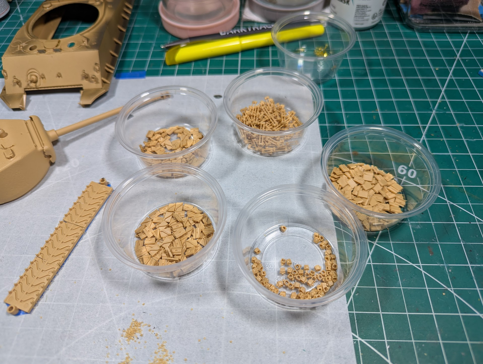
I spent an unholy amount of time finishing the tracks. I broke bags on this kit long ago, was very interested to see how they worked. In a nut shell each segment has a "pin", four pads (2-inner + 2 outter) and an "eye" that keeps them between the rollers. Instructions say use 76 links per side, I did not bother measuring or trying 75 or 77, I generally try to do as instructed. The rear idler wheel is adjustable as in real life, so not worried about the slack.

1762130579052.png

At the 12-o'clock position are the "pins", in this case both the link you are working on and the adjacent one are together, so each part is 2 pins. At 3:00 is one type of outer pad, at 5:00 are the eyes, 7:00 is the other kind of outer pad, and 11:00 are the inner pads, symmetrical for outer and inner thankfully!

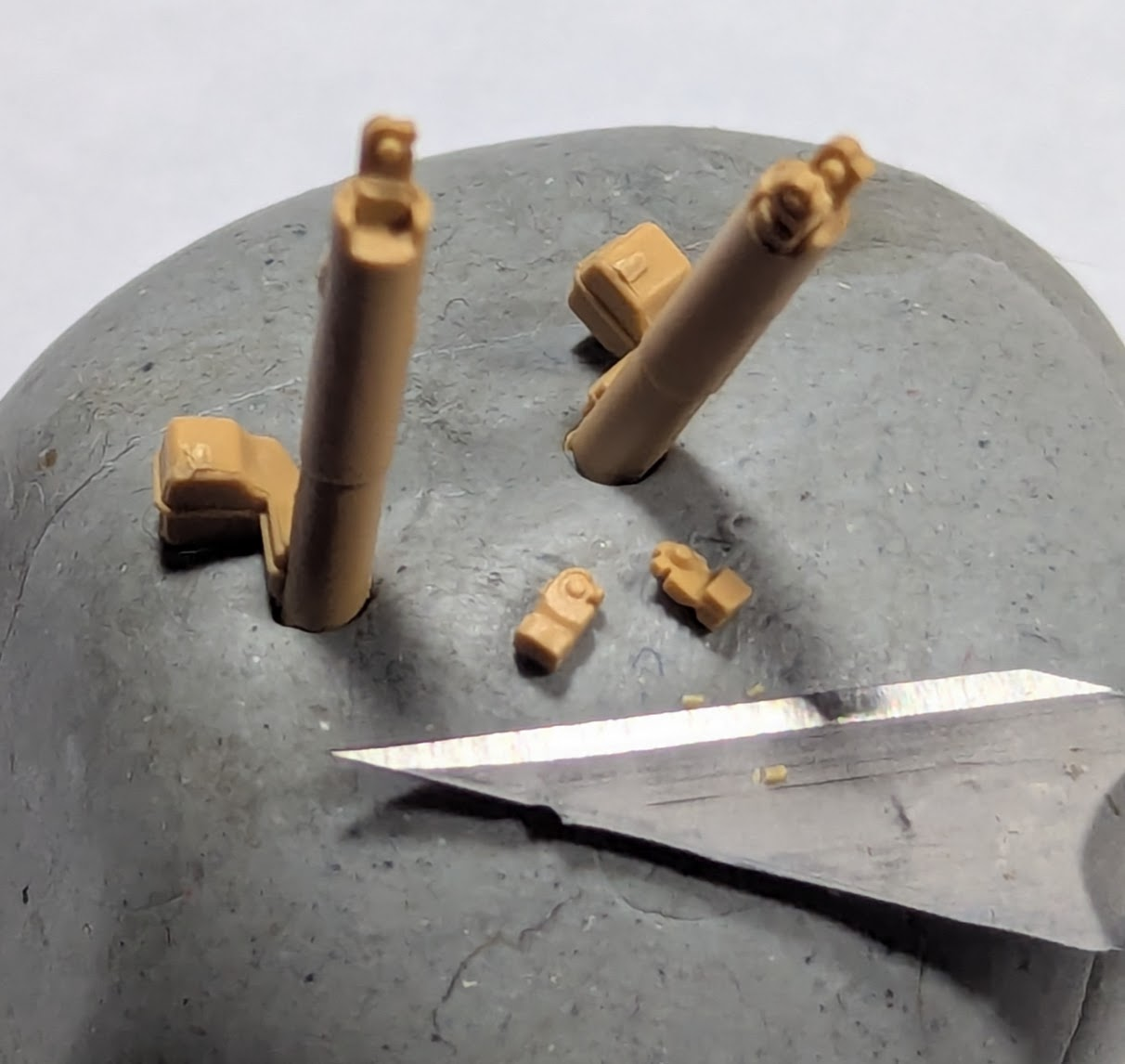
You can barely see it here, but that small pile or orange dust is part of what I cut off. Each part hade to be trimmed, no matter how carefully they were cut from the sprue. It took me 5 to 6 hours to clean them up, not kidding!

1762130828045.png

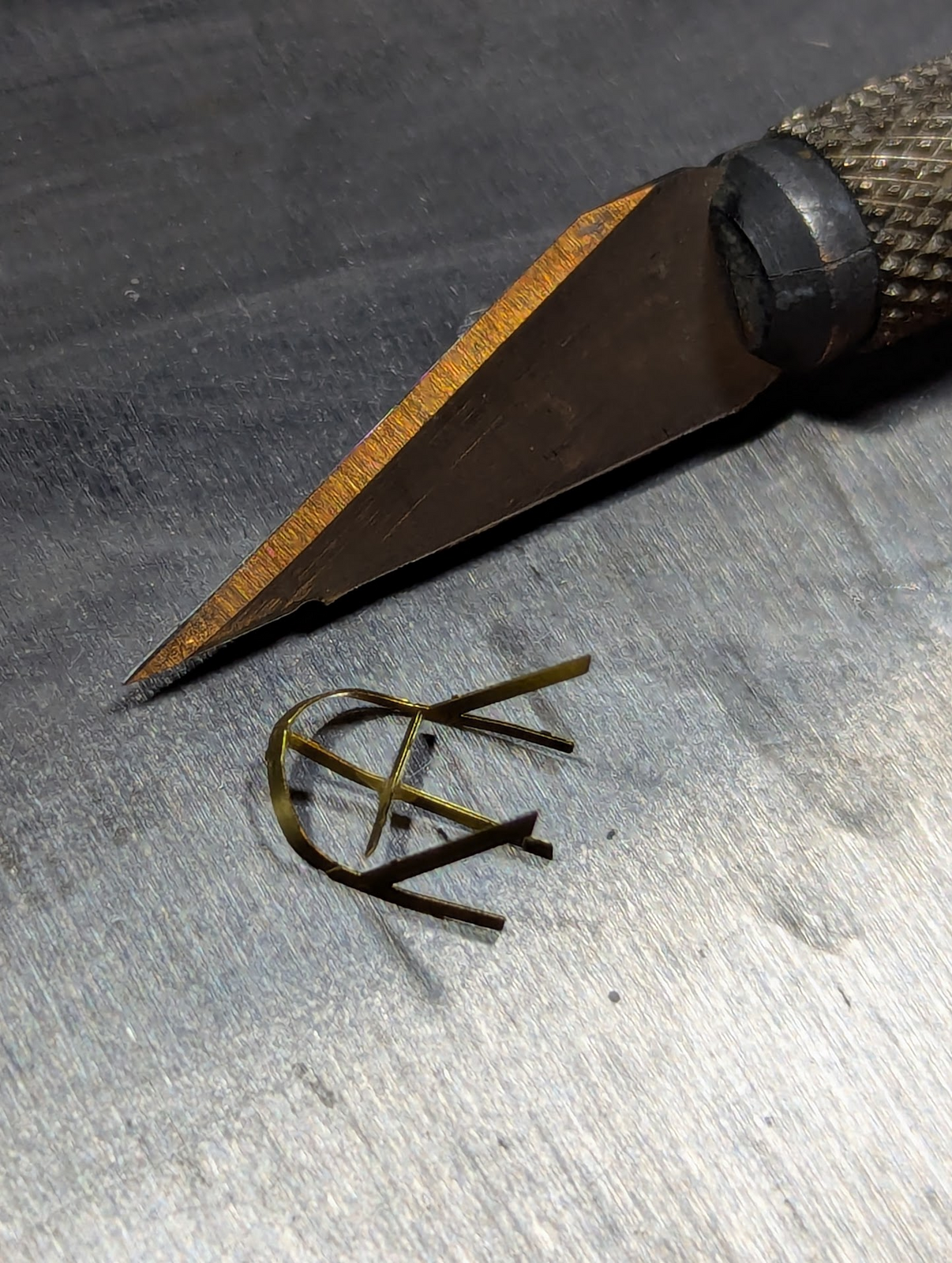
There was also some PE bits, the guards around lights and other do-dads (sorry jaxx!), the one shown above is three parts, obviously not finished. You can see some of the PE parts in the cup at the top of my previous pic.

1762130934674.png

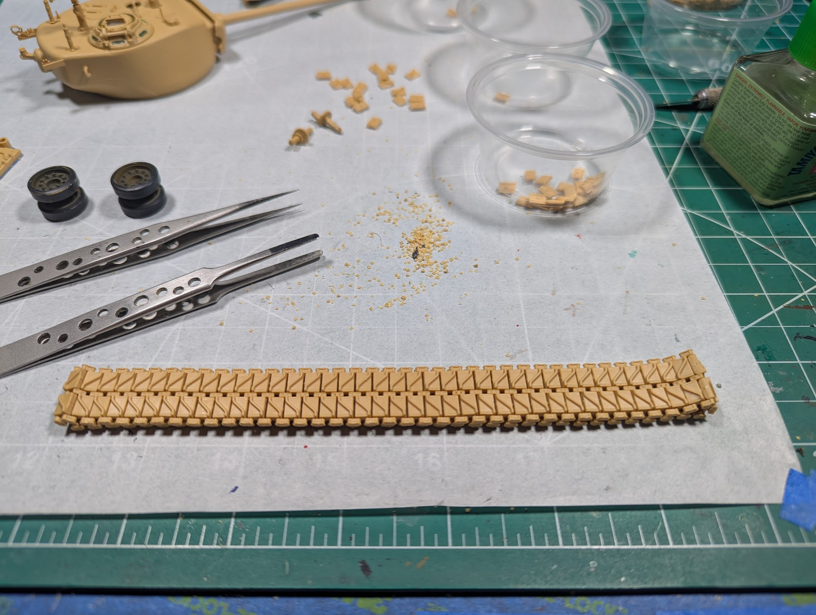
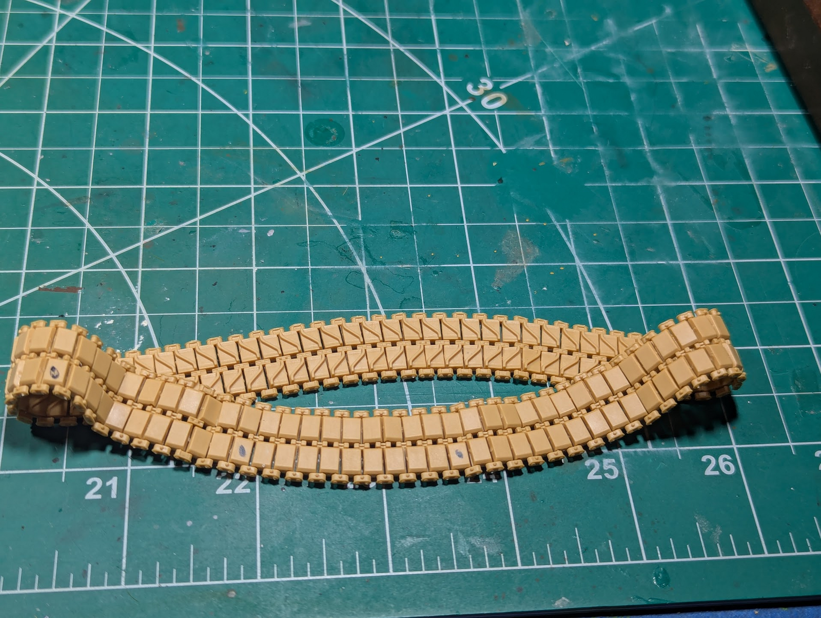
Here's a completed track loop minus the eyes, there are 76 of them per-side.

1762131126014.png

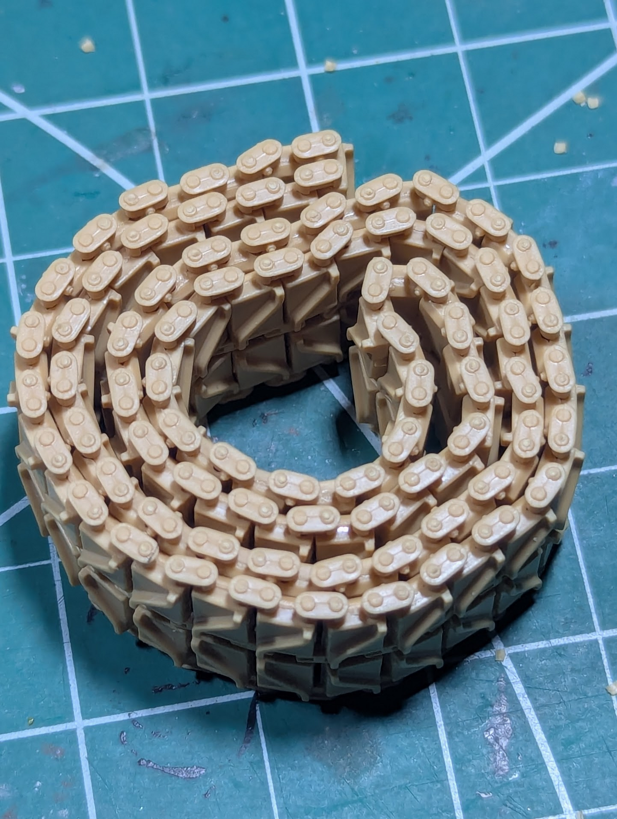
Another view of the workable track. Those pins have an inner and outer side too, is is VERY easy to get them to fit but be wrong. I confess this one is correct, the other side has some bassackawards though.

1762131226193.png

I flipped it inside-out here, to attach the eyes. In real life the smooth side is what was in contract with the wheels, but I was thankful how flexible these guys were, silky smooth, this allows me to put the eyes on much more easily. The little black marks are my counting method (a mark every 10th link), so ignore that :-)

All in all; I am very happy with how the tracks worked out, but I think it will be a long time before I do these again. I mentioned 5 or 6 hours of cleaning, I think it was close to that to assemble. Once painted, weathered, and covered with mud/muck,...I'm really wondering if the juice was worth the squeeze.
 
The turret is mostly complete, left Ma-Duece off her mount for now, masks the clear view ports, waiting for paint.
You've left off the loader's periscope, and I see the remains of an attachment point on the handle of the loader's hatch :) Also some mould seams left to clean up, especially prominently on the hinge of the commander's hatch.

I think it will be a long time before I do these again
My feelings exactly :) After I finished a set, I figured I didn't want to build another in the foreseeable future.
 
Yep i remember those tracks were time consuming when i did mine, and those light protectors were so delicate to mess with. :) Good job :)
 
You've left off the loader's periscope, and I see the remains of an attachment point on the handle of the loader's hatch :) Also some mould seams left to clean up, especially prominently on the hinge of the commander's hatch.
Yup! One mistake I made was not seeing the difference in the clear parts of the periscopes. The two on the front deck (driver and radio-operator?) and the loader looked the same but are not quite. So the clear bit extends further on one than the other two. Do not think I can fix that without messing things up more.

I did plan on cleaning up the commander's hatch, it is just sitting there, but did not see the sprue gate remains on the handle of the hatch. Thanks for the help!
 
You can always glue in the round base and the flap, but no actual periscope. The real thing was removable from the mounting, and the flap over it was spring-loaded to close the opening. Here's a training film about the M10 3-inch gun motor carriage where the driver and assistant driver show the drill for buttoning up, including fitting the periscopes into their hatches:


The Sherman's periscopes, including that for the loader, were exactly the same, even if the vehicle was different. From 2:40 you can also see the driver opening his hatch, and removing the periscope first.

(BTW, the two guys in the front were the driver and assistant driver, the latter also — or primarily in practice — being the bow gunner. He only operated the radio in command tanks that had an extra set located in the front right sponson. In German tanks, though, he was radio operator first, bow gunner second and not an assistant driver at all.)
 
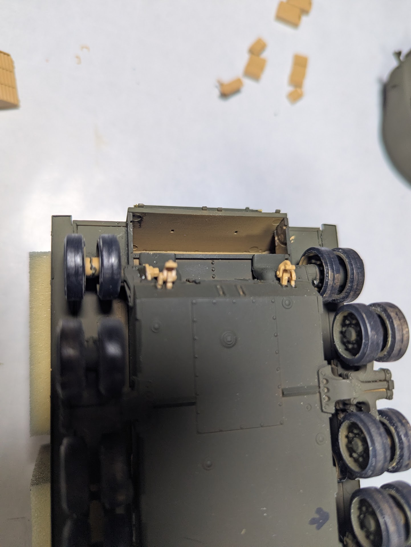
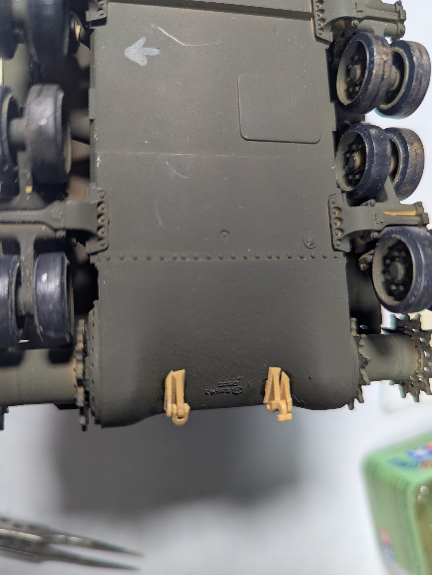
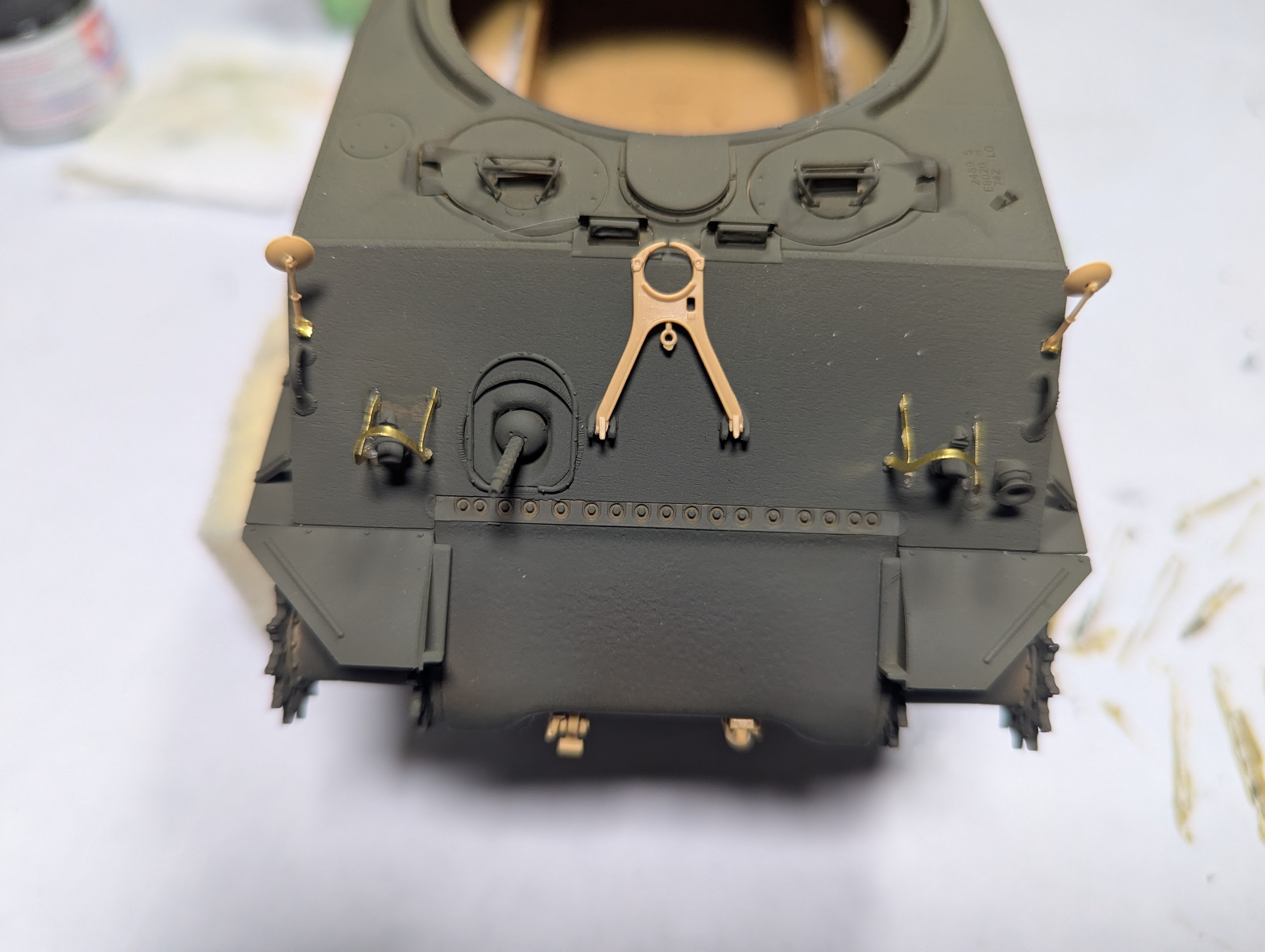
I'm still working on this, pull it out and do some stuff, then put it away when feeling frustrated. Here's a couple of shots showing lots of itty bits.

1779471626280.png

1779471644076.png

1779471663188.png
1779471677489.png


I will not say it is a problem with the instructions, they are quite good in fact, hoiwever they (and this kit in general) are a bit over my head. I think RFM kits are intended for people with more knowledge of the subject matter. Below is a perfect example.

1779471790863.png

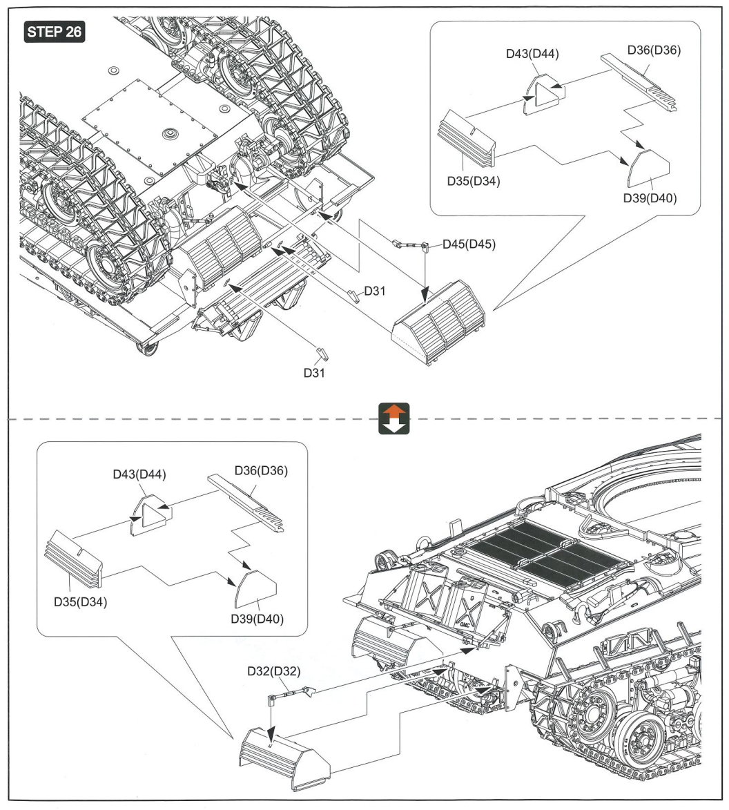
Step #26 is the exhaust diffusers (?), from what I can tell they can be mounted in one of two different ways. But which one is right? If I chose the red arrow (top) they will cover a hole shown in the first picture of this post, in the bottom option they ride below the shelf holding the fuel/water cans.

How do I decide?
 
I'm still working on this, pull it out and do some stuff, then put it away when feeling frustrated. Here's a couple of shots showing lots of itty bits.

View attachment 189996
View attachment 189997
View attachment 189998View attachment 189999

I will not say it is a problem with the instructions, they are quite good in fact, hoiwever they (and this kit in general) are a bit over my head. I think RFM kits are intended for people with more knowledge of the subject matter. Below is a perfect example.

View attachment 190000
Step #26 is the exhaust diffusers (?), from what I can tell they can be mounted in one of two different ways. But which one is right? If I chose the red arrow (top) they will cover a hole shown in the first picture of this post, in the bottom option they ride below the shelf holding the fuel/water cans.

How do I decide?
I'd view that as an option and which do you prefer? I don't think they're going to suggest a version that wasn't made so to me it's personal taste.
 
so to me it's personal taste.
All good bro...what is your preference?

Asking because I have no idea, not trying to put you on the spot.

If I intend to put anyone "on the spot" I'd do this...

@Jakko , what is the deal with these parts, what is right and more importantly, what would you do?
 
All good bro...what is your preference?

Asking because I have no idea, not trying to put you on the spot.

If I intend to put anyone "on the spot" I'd do this...

@Jakko , what is the deal with these parts, what is right and more importantly, what would you do?
Haha. Well I'd probably opt for the bottom option, under the fuel. If you make any mistakes you could always torch it and say the fuel leaked into the exhaust!
 
Well I'd probably opt for the bottom option, under the fuel.
I'm leaning that way. While not a Sherman expert by any stretch, I do not think I've seen them sticking out from underneath, at least not in the movies
:)
 
More thoughts on unecessary detail...

1779661899812.png


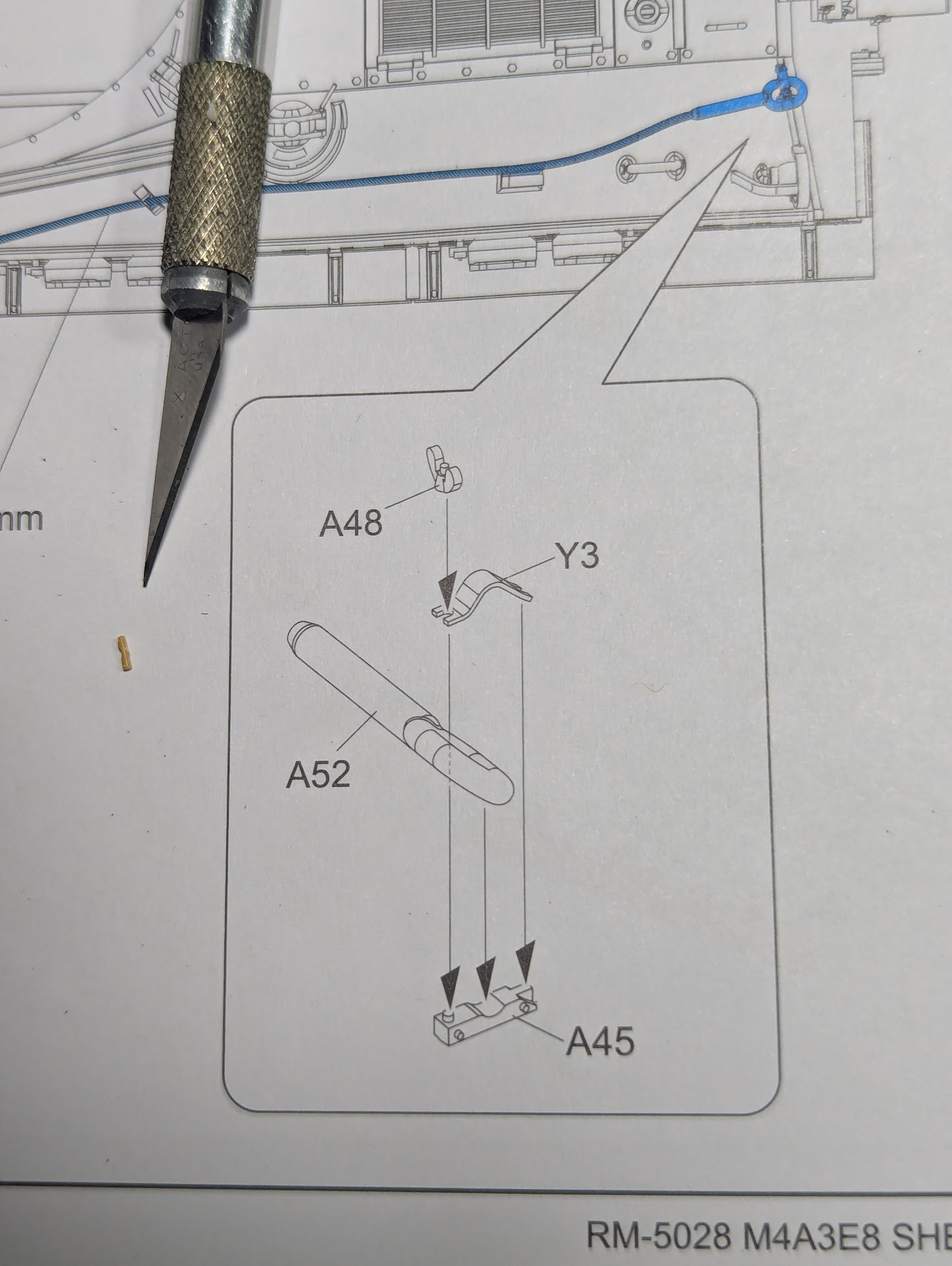
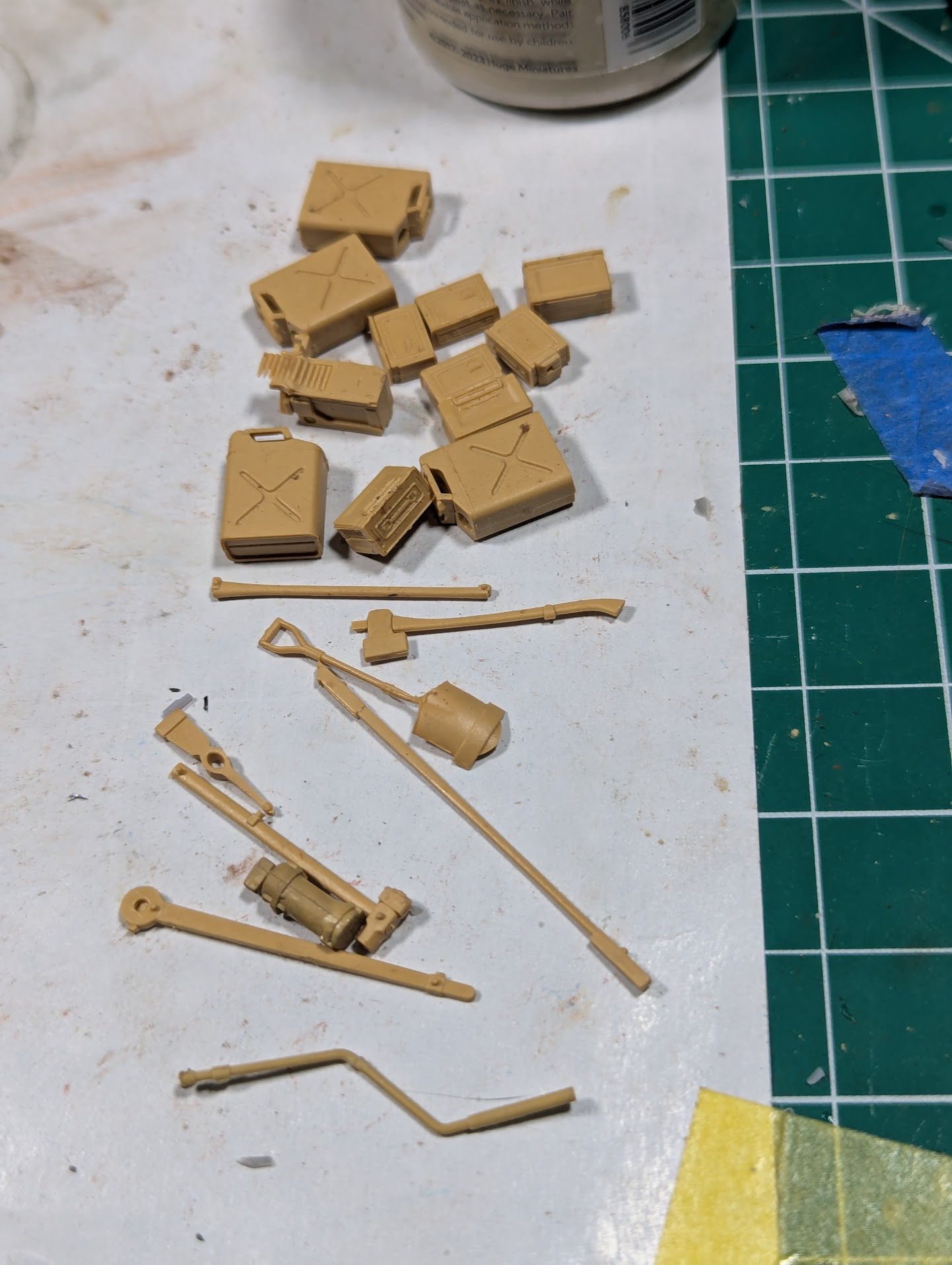
The tow cable end-buckles are held in my brackets that are (presumably) welded to the hull. The kit makes those brackets a separate part not molded-in. Part #45 is that bracket, Y3 is a PE bit that is hinged on one side in RL and the free end held down by a giant wingnut.

RFM thinks each of these assemblies should be 3 parts assembled by the modeler. Part # 45 is that small orange bit near the tip of a #11 blade, wingnuts are even smaller.
 
More thoughts on unecessary detail...

View attachment 190233

The tow cable end-buckles are held in my brackets that are (presumably) welded to the hull. The kit makes those brackets a separate part not molded-in. Part #45 is that bracket, Y3 is a PE bit that is hinged on one side in RL and the free end held down by a giant wingnut.

RFM thinks each of these assemblies should be 3 parts assembled by the modeler. Part # 45 is that small orange bit near the tip of a #11 blade, wingnuts are even smaller.
I personally think this is going to create added depth and realism! It may also give you a nervous breakdown!
 
RFM thinks each of these assemblies should be 3 parts assembled by the modeler.
I agree with them, for the most part :) These are clasps for the tow cable, and it was stowed in different ways IRL, so having the clasp as separate parts allows you to do that. They would have done better to mould Y3 in plastic, IMHO, because it's a fairly tine part to bend correctly.

As for the wing nut … On my Meng M4A3 I used a Tiger Model Designs clasp and that nut just pinged away out of my tweezers, never to be seen again. Yes, it is too small, at least for the likes of me.
 
A57 and A58 do. The way to fix the shock absorber, at least on the Asuka version and so almost certainly here as well, is to put the pin on A29 through the hole at the top of a suspension arm, then glue A57 or A58 to A29 and press it firmly in place (easily done between thumb and index finger). This will let the shock absorber pivot on the suspension arm, and because it can do that on both sides, the whole suspension is workable.

You do need to be very careful with the glue, though: a small drop of Tamiya extra thin on the flat on A57 or A58 will do.


You must fit those before you add the shock absorber. There's no way to get them in afterward.

And that's why I mentioned that it's much easier to add the suspension arms to the hull bracket first. If you do it like RFM (and Asuka) suggests, you have two arms that are connected only by the fairly weak hinges on the shock absorber, but must somehow manoeuver and hold the springs between them and stick both onto the bracket. But if you put them on the bracket first, like you have done, all of it's much more solid, making it far easier to put in the springs. For one thing, they won't drop out as easily due to gravity.


I've mentioned it before, but I generally regard the instructions as a guide for where to put the parts, not as the order in which they should be glued together :) There are exceptions, but that's a matter of keeping your eyes open to spot those.
This kit is my stash, along with the Fury accessories kit. I appreciate knowing what I'm up against.
 
the real tank was an M4A2, not an M4A3 like most (all?) kits that portray it :)
Either way it was not an E8.

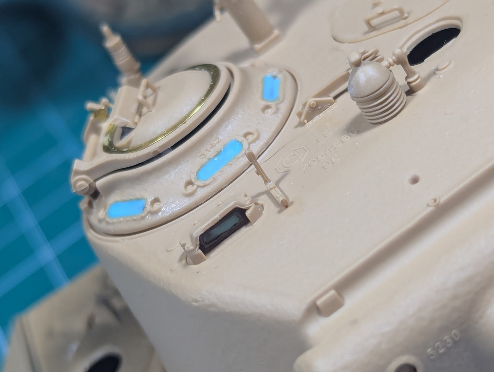
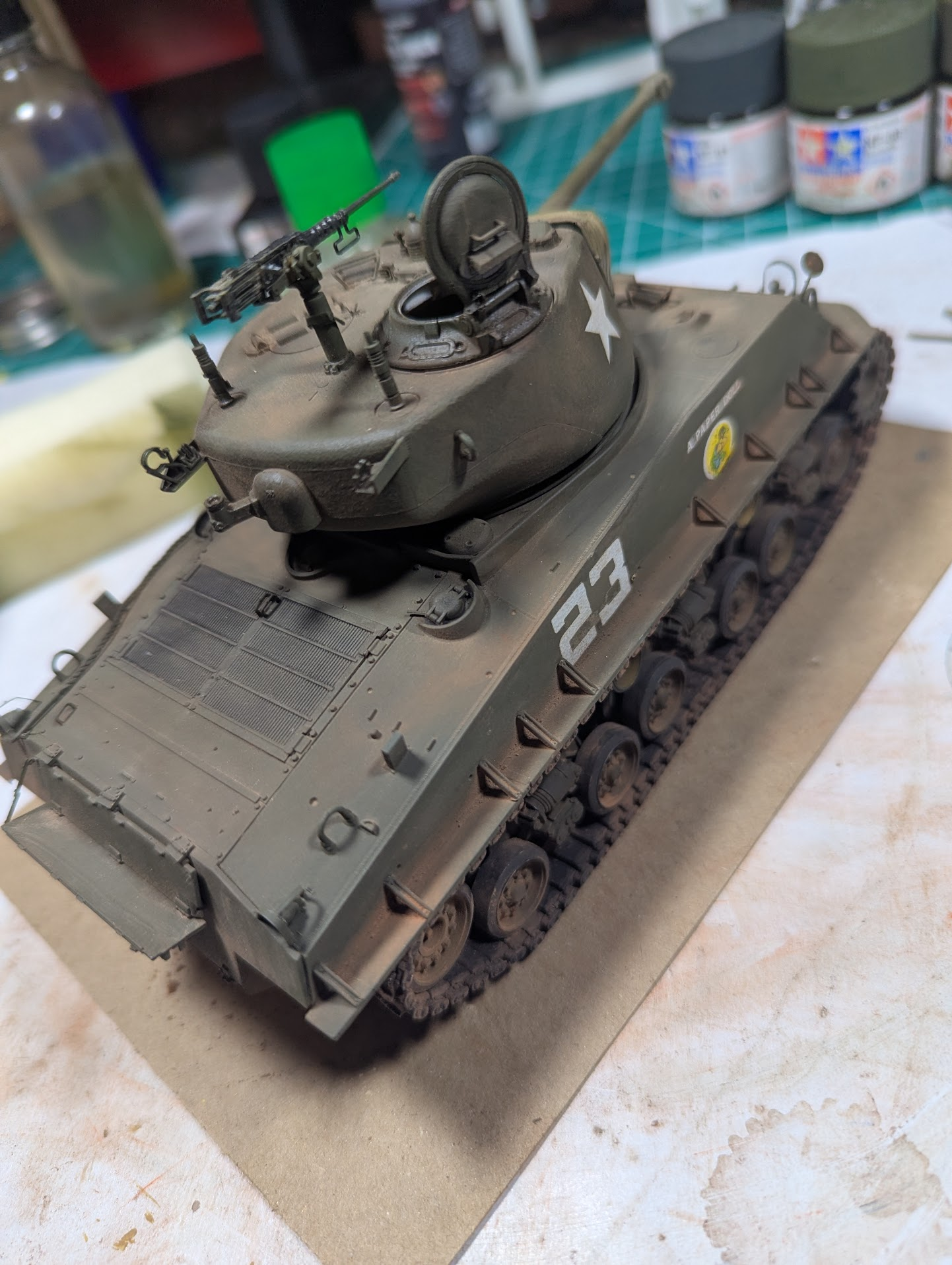
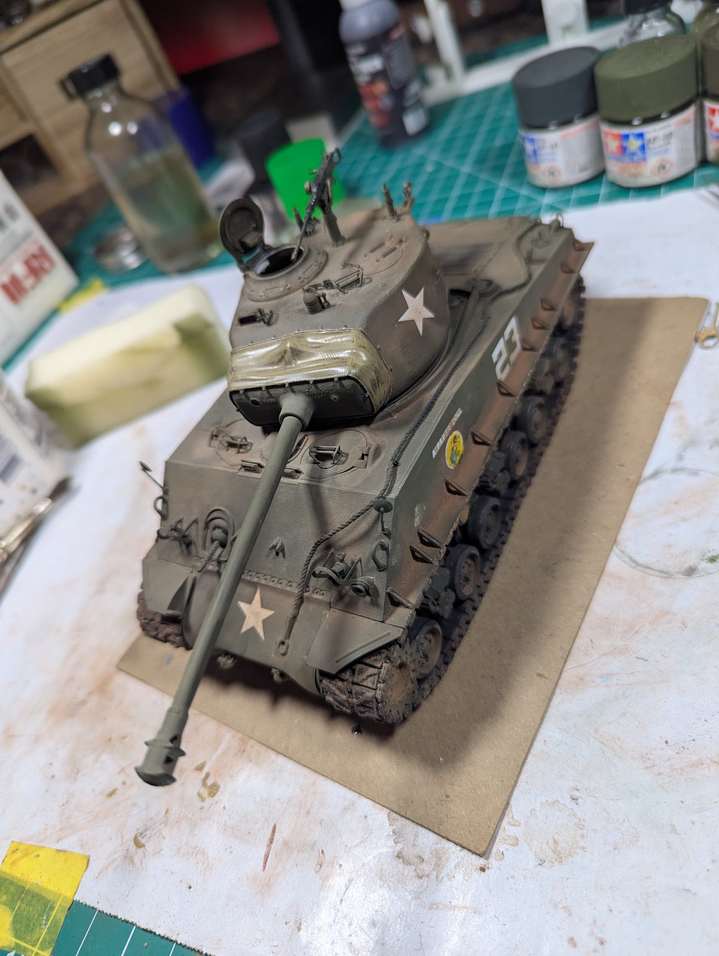
But...other than exterior bits missing, mainly the tools, do you see anything that should be addressed before a clear coat?

1781487423621.png
1781487395084.png


The vision ports have liquid mask over them, I want thew glossy part to show when I peel it. Same with the mirrors, will put a "chrome" on them at the last minute.
 
Either way it was not an E8.

But...other than exterior bits missing, mainly the tools, do you see anything that should be addressed before a clear coat?

View attachment 192802View attachment 192801

The vision ports have liquid mask over them, I want thew glossy part to show when I peel it. Same with the mirrors, will put a "chrome" on them at the last minute.
Might want to dust it off. That thing looks like someone has been driving it down a dirt road or something!
 
do you see anything that should be addressed before a clear coat?
There's no gun travel lock. Or will you also fit that after the clear coat(s)? It does look kind of like you have the mounts for it upside down on the glacis plate, but it's hard to be sure from the photo.

You've also missed the hub cap on the idler wheel, at least on the right (I can't make it out too well on the left) and one of the stays on the stowage shelf — there's one on the left only, but there should be one on the right, too.

Oh, and the commander's hatch can't be vertical unless someone's holding it. It wil fall to about 45° open, as its hinge has flats on it that work as stops.
 

Latest posts

Back
Top