Sherman III of 3 County of London Yeomanry, Sicily

Scale Model Addict - Model Tips, Guides, Tools & Tech, Tutorials, and Community

Help Support Scale Model Addict:

Jakko

Well-Known Member
Joined
Oct 9, 2024
Messages
2,393
City & State/Province
Netherlands
A kit that I've had in my stash for a number of years is a Sherman III by Asuka, and now that my British French tanks are close to being finished, I decided to start this one:
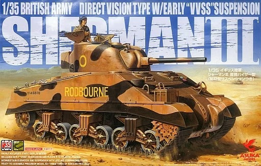
Asuka 35-017.jpg


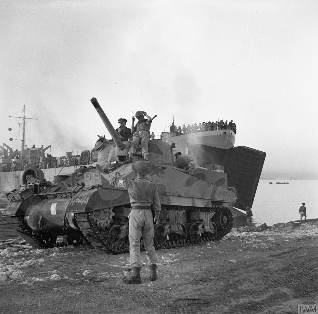
This kit includes decals for a tank named Churchill of 3 County of London Yeomanry, which is to say, this tank:
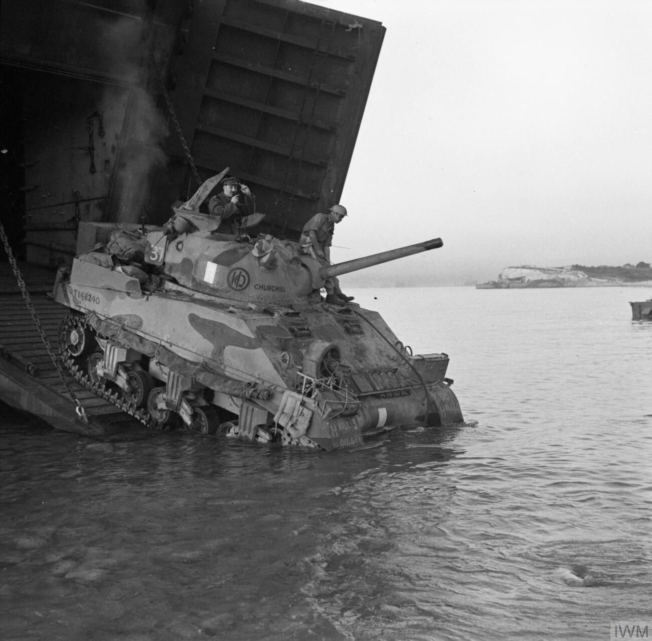
Sherman III “Churchill” (NA 4262).jpeg
(source)
Sherman III “Churchill” (NA 4263).jpeg
(source)

And as I have an edition of this kit that includes a Value Gear set with stowage for the rear deck, including "in" the racks that have been improvised from the rear sand shield sections, I intend to build this one from it. Not with the deep-wading gear that's on the tank in the photos, but as it might have looked slightly later during the fighting on Sicily.

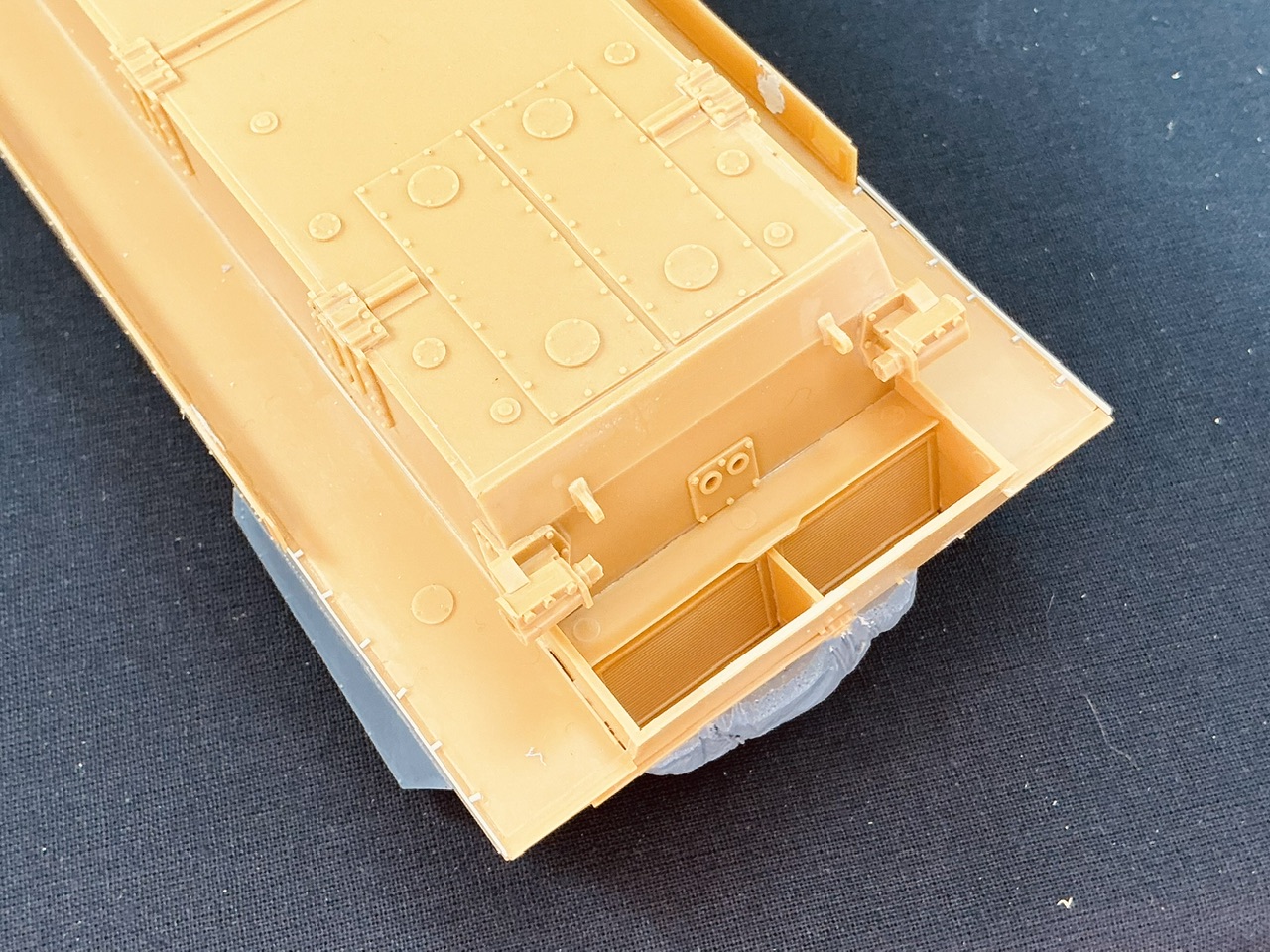
I started with the underside of the hull:
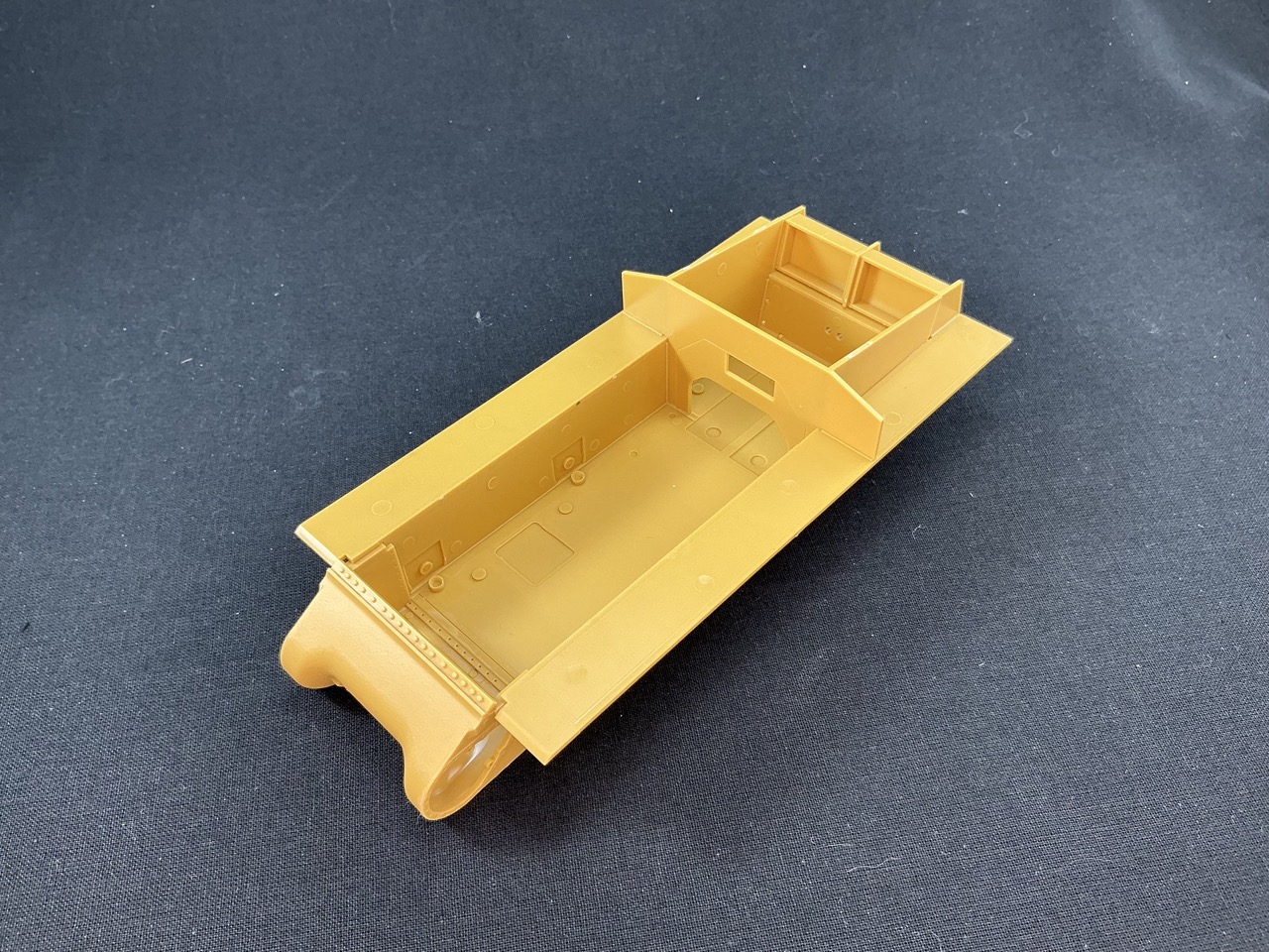
IMG_2927.jpeg


Very little to report there, it's an Asuka hull so even though it's made up of flat plates, it all fits pretty much perfectly.
 
They look like staged photos, the clarity is so high, not meaning the tank did not disembark there, but that the CO was posing in the commander's hatch while the press was present.
 
Not sure, my guess is that he's out of his hatch and talking into his microphone to guide the driver, who only has a single periscope to look out of in both photos. That's probably also why the other man is sitting on the front of the turret.
 
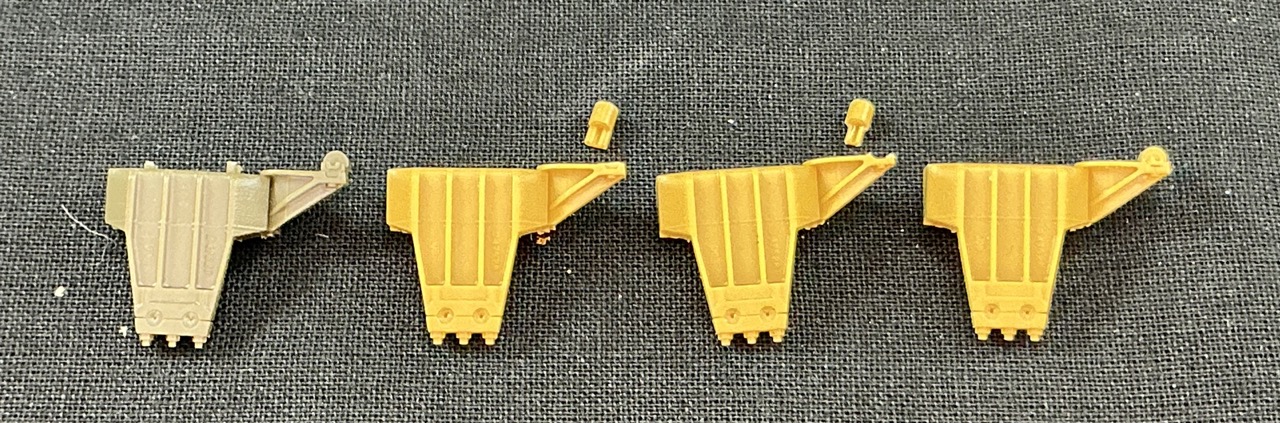
Looking at the pictures of the real Churchill, I noticed it had bogies without the riser between the return roller and its mount. Early Shermans didn't have those risers, but they were later installed in the factory and, IIRC, also sometimes in the field. Asuka gives you two parts for different bogies, but those are a flat mount with risers, and an angled mount (that was designed to remove the need for the risers). What to do?

IMG_2928.jpeg


After some thought and a quick trial, the solution was actually very simple.
  1. First from left a part straight from the box (but green, because it's a leftover from another Sherman).
  2. Second from left, I cut through the riser with a sharp knife, separating the axle for the return roller from the mount.
  3. Third from left, I used the side of a file to make the "channel" in which the riser sits and used a knife and a file to remove the remains of the riser from the axle.
  4. All the way at the right has the modified axle glued into the channel.
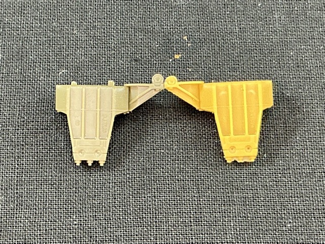
Here's a comparison with an unmodified part:

IMG_2929.jpeg


I don't intend to do this on the inner halves of the bogie — it's only visible on the outer parts, after all. On the inside, I'll just cut the axle off vertically and glue it back to the mount a little lower.
 
As an Amazon Associate we earn from qualifying purchases. Product prices and availability are accurate as of the date/time indicated and are subject to change.
Your attention to details like that, and your ability to execute on them never cease to amaze me!
It helps that I'm aware that those riser blocks were introduced at some point, which means that I can look specifically for them on tanks that may be early enough to not have them. All of which, really, is to say that over the years I've built up a good amount of far more knowledge than is good for me about Shermans ;)

As for making this correction, it turned out to be a lot easier than I had expected it to be. It was a little fiddly, especially trimming and filing the little bracket on the axle to fit in the slot in the bracket, but it was not actually difficult by looking and working carefully. I didn't even need to combine two parts like you often have to do with corrections like this. Of course, if I would have had to use two parts, Asuka Sherman kits are ideal for that because as I said, you get two bogie bodies: had it proved impossible to remove the axle without destroying it, I could just have taken the axles from the bogies with upswept roller mounts. Or from any of the dozens of bogies of both types I have in my Sherman spares box :)
 
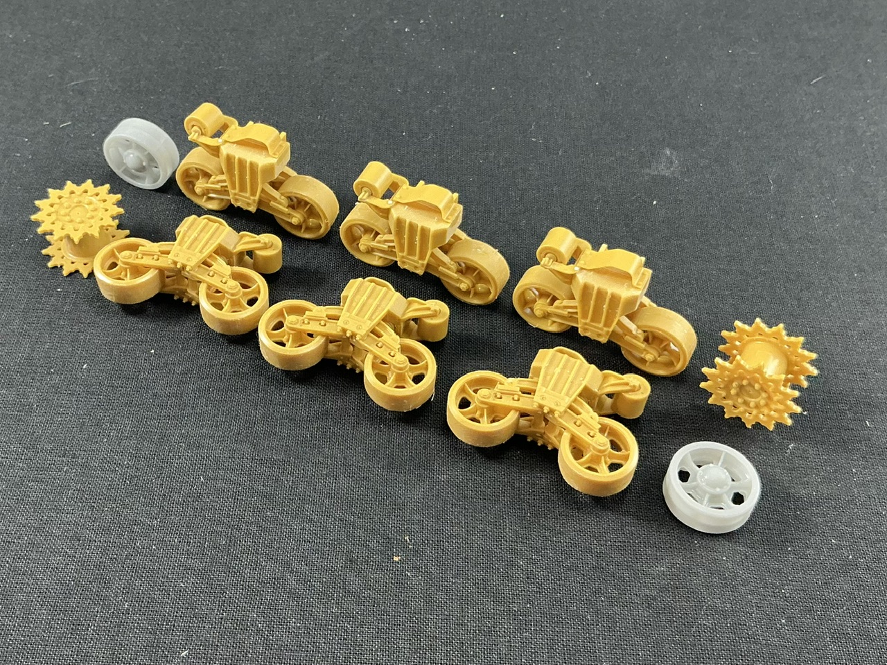
And that's the bogies done:

IMG_2933.jpeg


At the front of each, I drilled four holes using a jig I made years ago, and added a bolt on the top (there should be one on the other side too, but it's all but invisible when the bogies are on the tank). The idler wheels are 3D prints my brother made for me, from a file by Robert Lockie on Cults3D. I'm using this one mainly because the Asuka wheels don't have the inward-turned rim the real wheels do.

Onto the lower hull, I added the upper:

IMG_2932.jpeg


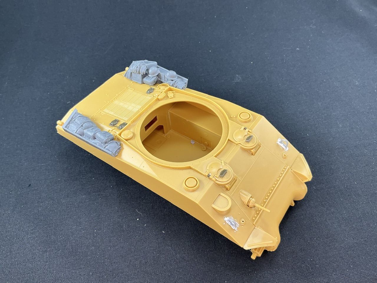
The green parts are because my kit is missing two sprues, with the D and G parts (that is, one sprue with both D and G parts, times two). Many of the parts on those, you usually don't all need, like fuel cap covers, periscope lids, etc. so I have plenty in my spares box. The hinges for the drivers' hatches are not something you usually have spare, but I did from my Sherman BARV. But even if I hadn't had them, they would have been very easy to make from some plastic card.

The lifting eyes on the glacis are from Dragon. They're also on sprue D, but the ones in the kit are incorrect for this tank anyway: Churchill looks like it was made at Fisher Tank Arsenal, and those tanks all had lifting eyes on "pads", which the kit doesn't give you. Happily, I had some in my spares box, with putty added for the welds.

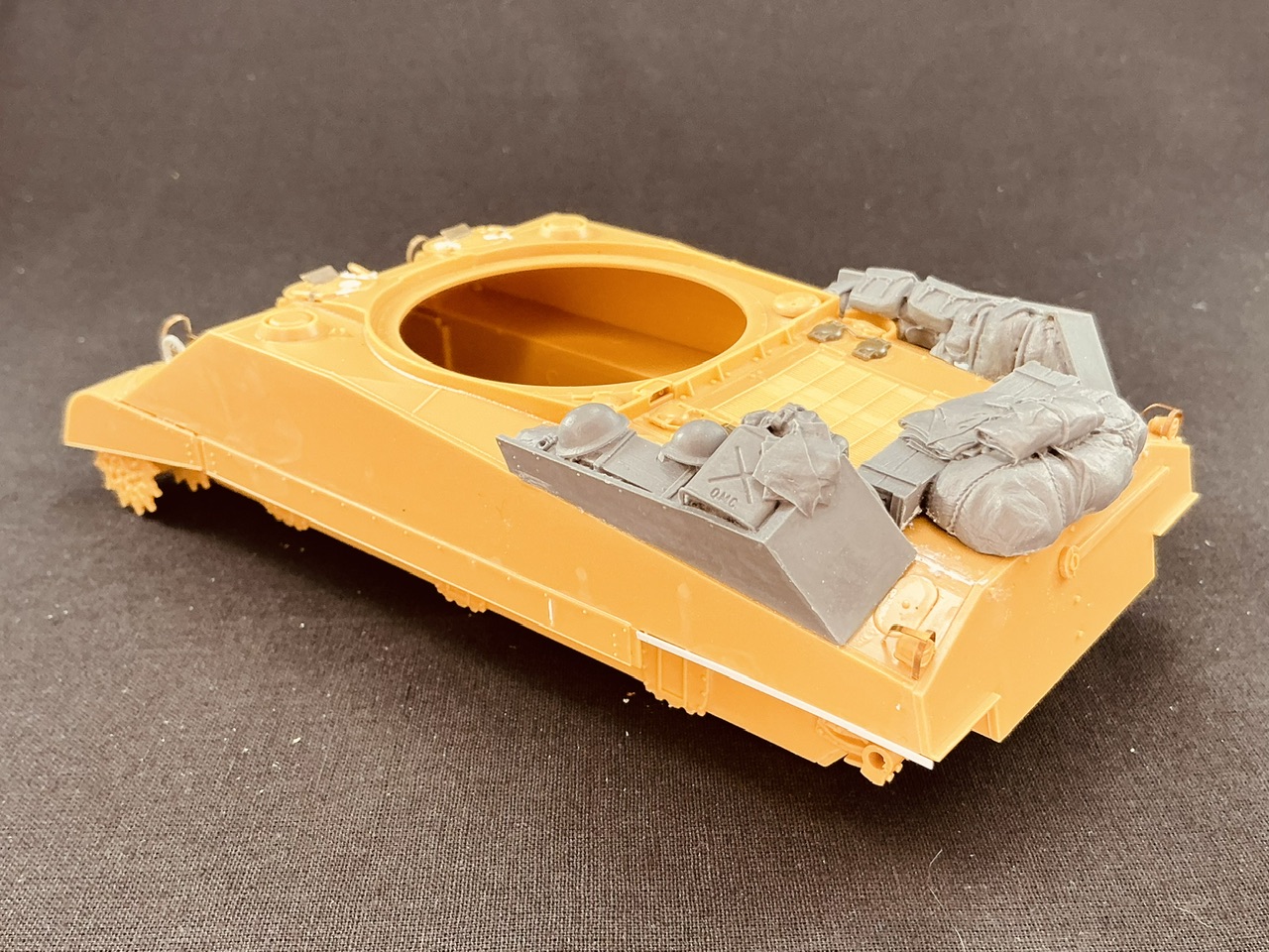
The grey parts on the back deck are from the Value Gear set that was in the box, but I had to adjust them to fit where they do now. They're made to fit further forward, so the cut-out for the fuel filler cap is too far back, which means it took some work to carve a new one in both parts.
 
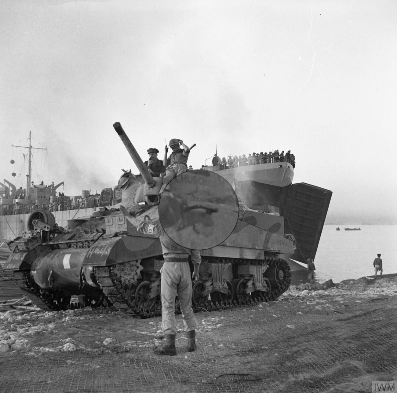
To me, figuring out the details of the particular vehicle in a photo is part of the fun :) For example: what is that thing that seems to be stuck to the left hull side, just visible to the right of the helmet of the man guiding the tank?

Bracket on hull side.jpg


It seems to be some kind of bracket or handhold, but there's nothing below it to suggest it's either for stowing stuff or to help climbing onto the tank …
 
I'd bet a dollar on the handhold idea. The maintenance boys at the field depot could knock those out in no time.

Other observations, that storage box (?) on the left front fender would obstruct driver's view at least to a degree. Either that negates the commenter opinion's that crews never did that, or it reinforces the (possible) staged nature of this landing scene.
 
It's an ammunition box, model B166. Given all the other stuff on the front, I suspect it was welded to the mudguard, as you say for extra stowage. The driver would have a hard time seeing it, judging by placing one on the model and looking over it at the periscope — it probably blocked his view a little if the periscope was turned to the left front, but that seems to be it. That spare roadwheel likely was more of a hindrance, but mainly to the bow gunner.
 
Great work Jakko.As you know im very partial to Shermans mate.Havent made one for a long time.
Richard
 
Always so interesting to read your posts...
Great to read that :)

As you know im very partial to Shermans mate.Havent made one for a long time.
Maybe it's time to rectify that ;)


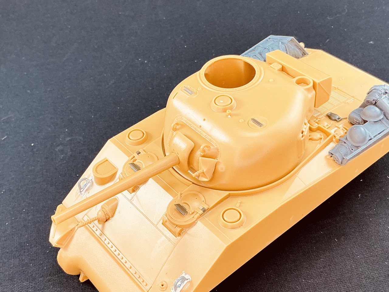
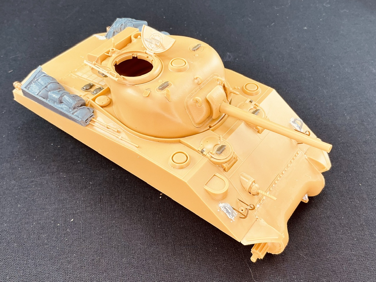
By now I've also started on the turret:

IMG_2941.jpeg


In the photo of the real Churchill after it had come ashore, you can just make out that it had the extra shield on the coaxial machine gun. For the 75 mm gun, I used the early barrel with a flared end instead of the later one that has a constant taper — you get both in the kit. Because Churchill's barrel had its muzzle taped up for wading, it's not clear which of the two it actually had, but based on the other early features (hull with direct-vision flaps, gunshield without "wings", bogies with skids that don't curve forward) it seems a logical assumption to me. In any case, you can barely tell the difference even when you know what to look for ;)
 
Great to read that :)


Maybe it's time to rectify that ;)


By now I've also started on the turret:

View attachment 155101

In the photo of the real Churchill after it had come ashore, you can just make out that it had the extra shield on the coaxial machine gun. For the 75 mm gun, I used the early barrel with a flared end instead of the later one that has a constant taper — you get both in the kit. Because Churchill's barrel had its muzzle taped up for wading, it's not clear which of the two it actually had, but based on the other early features (hull with direct-vision flaps, gunshield without "wings", bogies with skids that don't curve forward) it seems a logical assumption to me. In any case, you can barely tell the difference even when you know what to look for ;)
Sadly Jakko i culled much of my Sherman stash(Sin!!!!!),Think ive only got x2 Tamiya M4a3s,X2 Tamiya early M4,Some Tasca sprues,Resicast Sherman V direct vision conversion.I do regret the cull as i had 4 Tasca ones and Dragon,Im sure i will buy them again no doubt!!
 
Sounds like you hung onto the worst of the bunch :( Though the Tamiya kits do build easily, of course.
 
Sounds like you hung onto the worst of the bunch :( Though the Tamiya kits do build easily, of course.
Yes indeed.I thought id never build them and got a load of aircraft kits.One of the Tamiya A3s will become a Pacific one with nails on hatches.The earlier ones maybe just tinker around and change the hoods and aerial pot.Maybe a Sherman 1.Hoping that a Sherman V appears in DV!!! In plastic form
 
For a V DV you could buy an Asuka upper hull with DV, like from this M4A2 I'm using here, and cut out the hatch surrounds to put onto the hull that comes with an M4A4 kit?


IMG_2943.jpeg


More details added to the turret, including that I cut off the mount for the searchlight to the left of the ventilator, because this was introduced later than this tank would have left the factory. That also goes for the devices on the commander's hatch doors, which lock them in the open position, so I also cut those off from the outsides of the hatches, but that's not visible in the photo. The lifting eyes on the rear sides of the turret are in the "high" position like on the real Churchill, which again points to it being an early tank. The base plate for the British sun compass is just visible in the picture of the tank as it leaves the LST, so I also put that on, as well as British aerial bases.

On the hull, I cut away the bullet deflector in front of the row of bolts, which is one of those annoying jobs that I always kind of enjoy doing :) If you look at how the five spare track blocks lie on the glacis in the photos of the real tank, it seems very unlikely that Churchill had that deflector — again a sign of a very early production M4A2. The etched guards for the head- and taillights are not included with the kit (they weren't missing, they're not supposed to be included with this kit in general) but come from the M4A2 I converted into a BARV, which doesn't need them at all so they came in handy here.
 
That sounds a good plan Jakko.I was toying with the idea of cutting and swapping glacis plates from the DV M4A2 and the M4a4 hull.Think your suggestion is better.Some delicate cuts with a fine saw is less fraught with danger then my glacis chopping.I do like the DV tanks,Think they have character and the U.K had plenty like your Sherman 3,Im a big U.K sherman fan well any to be honest.Awaiting your progress
Richard
 
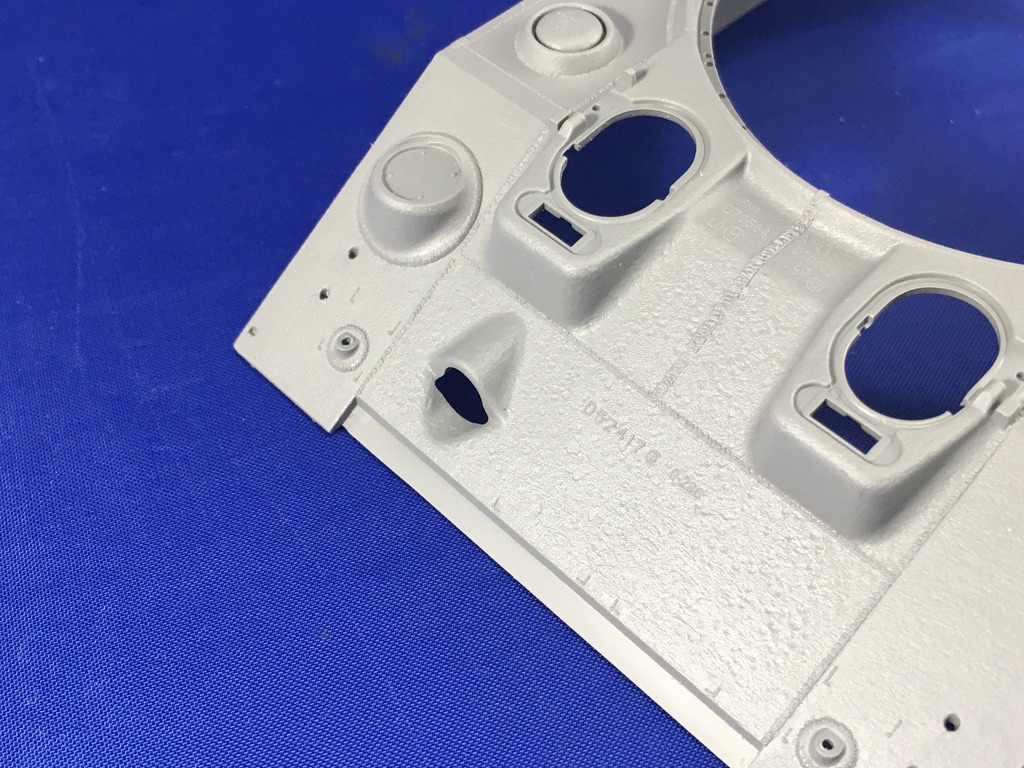
If you were to swap the whole glacis plate, you would almost certainly also put an antenna base (the round "pot" on the right glacis) on that's incorrect for the variant you're building, as well as an incorrect pattern of welds for the plates that make up the glacis. Compare that on my model to that on an M4A4 (here by RFM), for example:

A38CE6FB-EBB8-448A-9A4B-DEC073C53926_1_105_c.jpeg


Those weld lines are as good as a fingerprint for identifying the factory that the tank came from.
 
Sounds a plan.I can never remember the different manufacturers foundry types,Always forget,I know the U.k used Alco Sherman 1s and a lot of Fisher M4a2s,Think i remember Fisher M4a2s held onto later features like padded glacis lifting fittings later on,The beauty of Shermans sooo many variants and not standard features on so many.
 
This model is an early Fisher one. The later Fisher tanks are easy to recognise because the hoods are angular rather than rounded, but other than the M4A4 and that, I always need to turn to Son of Sherman to work out from various details which manufacturer I'm looking at :)


Aside from sticking more stowage onto the back, I made a small correction to the engine deck to backdate it slightly: I filled the seams at the back to the left and right of the central part and scribed new ones slightly inboard. I also added the sand shields:

IMG_2945.jpeg


To do that, I first put the drive sprockets onto their axles, without glue, and then added the front two sections — because the rear part had of course been fitted to the engine deck to serve as a stowage rack. The middle portions didn't have a slot in them on the real tank, so I filled those by smearing putty into them from behind, letting it come out on the front and scraping it down once it had dried.

After that, I had another thing to figure out, because in the photos of the real Churchill it looks like there's a strip behind the middle section, but it doesn't appear to be the normal one that was welded to the hull to fix the sand shields to — this tank was too early to have those. But what was it? By looking closely at pictures of British Shermans in Italy, such as this one, my conclusion is that it's a strip that was attached to the little blocks that were welded to the undersides of the sponsons, which were the early way of fixing the sand shields. But I had cut those off because the instructions told me to … OK, put them back, then, and stick a bit of strip to them:

IMG_2946.jpeg
 
This model is an early Fisher one. The later Fisher tanks are easy to recognise because the hoods are angular rather than rounded, but other than the M4A4 and that, I always need to turn to Son of Sherman to work out from various details which manufacturer I'm looking at :)


Aside from sticking more stowage onto the back, I made a small correction to the engine deck to backdate it slightly: I filled the seams at the back to the left and right of the central part and scribed new ones slightly inboard. I also added the sand shields:

View attachment 155288

To do that, I first put the drive sprockets onto their axles, without glue, and then added the front two sections — because the rear part had of course been fitted to the engine deck to serve as a stowage rack. The middle portions didn't have a slot in them on the real tank, so I filled those by smearing putty into them from behind, letting it come out on the front and scraping it down once it had dried.

After that, I had another thing to figure out, because in the photos of the real Churchill it looks like there's a strip behind the middle section, but it doesn't appear to be the normal one that was welded to the hull to fix the sand shields to — this tank was too early to have those. But what was it? By looking closely at pictures of British Shermans in Italy, such as this one, my conclusion is that it's a strip that was attached to the little blocks that were welded to the undersides of the sponsons, which were the early way of fixing the sand shields. But I had cut those off because the instructions told me to … OK, put them back, then, and stick a bit of strip to them:

View attachment 155289
Yes im glad i bought The son of the Sherman when it first came out,Also picked up the Histoire and Collections book on U.k armour in Normandy,Great for deciphering the formations who used them.Ive still got a Dragon DV M4a2 to finish,This one is the later boxing with mid bogies.
 
There's a guy in my local club who is "VERY much into Shermans", ya'll should hook up for some beers!
This isn't by any change the guy who's building the barrel for the Dora railway gun that the other guy who's on here won in a raffle, is it? :)
 
im glad i bought The son of the Sherman when it first came out
I bought the original edition maybe five years ago when I came across it supposedly second-hand, except it was still in its plastic wrap when it arrived :) When the second edition was announced I decided to get it as well, despite the cost, and I'm glad I did.

Great for deciphering the formations who used them.
That interests me very little, TBH :) I have a hard time keeping a lot of them straight, never mind recognising them by their badges etc. Rather, I tend to look at photos and copy what I see there, or for generic models, use those for inspiration of what markings are reasonable.

Ive still got a Dragon DV M4a2 to finish,This one is the later boxing with mid bogies.
I'm not enamoured by Dragon Shermans, but I think at some point I'll get their Fisher M4A2, because the square drivers' hoods are so distinctive, and it's one of the few kits from which to build one. Unless, of course, I decide to start with an Asuka and convert the hoods with some plastic card :)
 
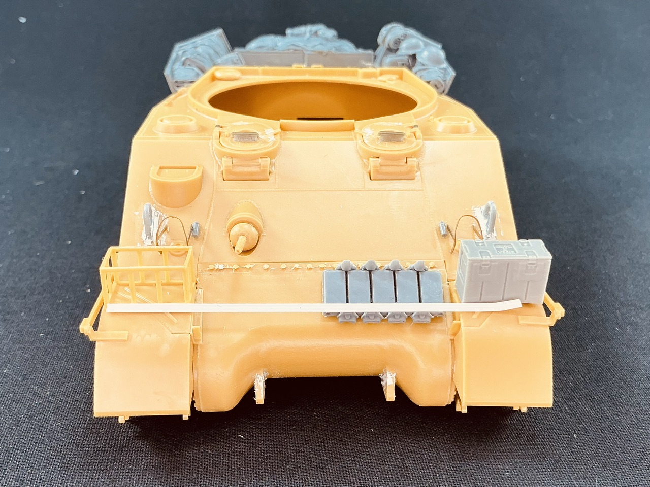
With the Sunshield rails attached to the sides, I moved on to the stowage on the front plate:

IMG_2947.jpeg


The rack comes with the kit, but I didn't fit the three 2-gallon cans in it, because this is where the spare wheel will go. The B166 ammunition box comes from Panzer Art, with a few bits of plastic card underneath so I could glue it to the mudguard despite the strengthening rib in that. The angle iron is two pieces of plastic strip glued together, 0.75 mm and 1 mm wide and both 0.25 mm thick. The track links are MiniArt, but not glued down yet. I wonder what the square objects are that are next to them on the real tank.

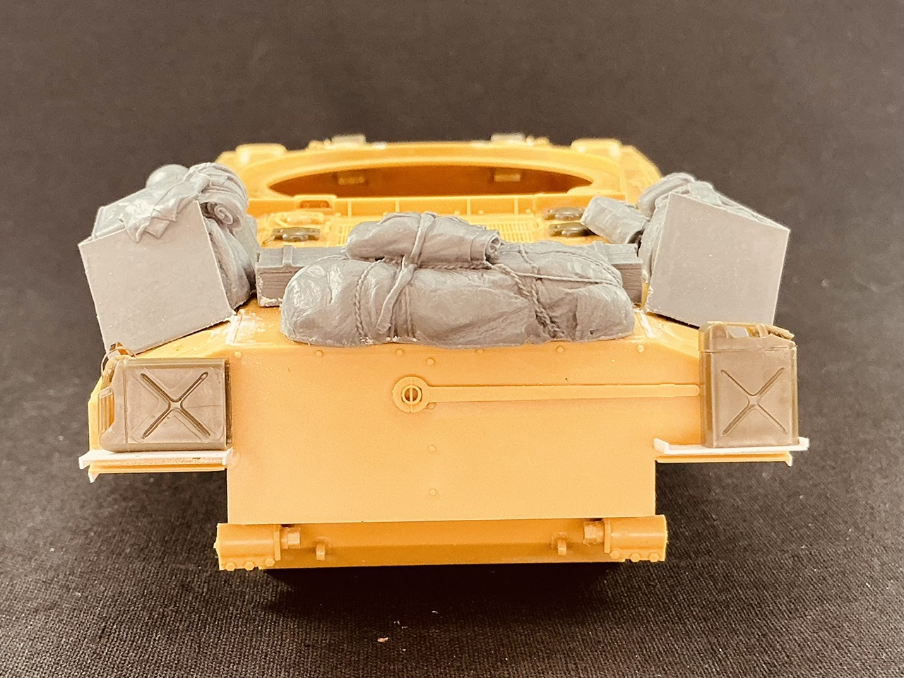
And the back:

IMG_2948.jpeg


Both photos of Churchill show a jerrycan on the back, and I think they're both for water and not for fuel. I used some from Asuka, with a little shelf under both. Oddly enough, it looks like there's an upward edge on the one on the right, but the one on the left seems to be very thick. I interpreted that as two similar shelves from steel plate, but one installed upside-down for some unexplained reason. They're simply made from 0.25 mm plastic card and a couple of bits of strip.
 

Latest posts

Back
Top