Polar Lights: NX-01 Enterprise: 1/350

Grendels

Active Member
Joined
Nov 24, 2009
Messages
9,092
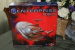
Well, I started on this project a couple of weeks ago, and I finally have found the time to do a little bit of posting. I bought the model off of Ebay as a warm up for the 1/350 1701-A Refit
IMG_3687.jpg

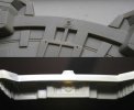
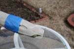
After doing a tape up, I decided to start with the nacelles, they will require the most work, both with lighting, and with seam filling. The directions reccomend that you paint the model first, but I still haven't figured out how to do some that, then go back and fill the seams, keeping the paint one shade. Here is an example of why I am worried about the seams:
IMG_3691.jpg

I am not sure how to fill this, and keep the textures intact. I won't get started on that for a little while, so I have time to figure it out.

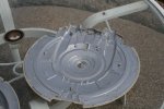
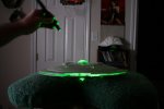
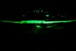
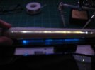
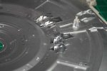
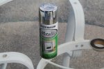
The first thing I did was lay out the parts, and throw some light block paint at it. I used Rust-oleum Metalized paint for this. Two coats, and it has done both light blocking, and put down a very reflective surface. When I get some time, I will post a test photo of this. (Used a green laser to illuminate the saucer section as a test.

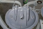
Here are photos of the saucer sections with the paint:
IMG_3696.jpg
IMG_3697.jpg

If you look closely, there is a broken pin on the above photo, shouldn't hurt the model at all.
IMG_3698.jpg

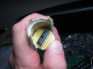
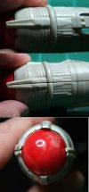
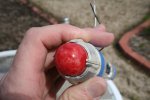
I am doing some preliminary painting, mainly with the nacelles, and the warp coils. In the show, the ball ends have a swirl pattern to them, I tried to replicate it:
IMG_3695.jpg


I used Tamiya clear red, let is set a bit, then brushed on some flat flesh, after drying for a few day, I added more layers of clear red. Gave a good pattern that the camera still does not pick up well. I did some trial runs on a clear plastic box before painting the ball ends just to make sure I was getting the effect I wanted.

Then I started on the warp coils. A couple coats of tamiya clear blue to start with:
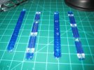
IMG_0550.jpg

Then I went back and looked at my reference photos (link for reference photos: http://www.ex-astris-scientia.org/scans/nx1.htm ) and found that the outside warp coils have only blue rectangles showing, with the inboard coils showing, blue except where some piping joins up with them. So out came the tape, and I taped it up, applied a few coats of flat black paint. I am still not done with painting these:
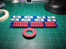
IMG_0552.jpg

The red tape is drafting tape, it is cheap at art supply stores and comes in widths of 1/8 and 1/4 of an inch. Nice when your parts conform to those sizes.
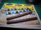
IMG_0553.jpg

I will post more photos of these when they are done. I still need to put at least one more coat of paint upon them, and then the sides of them need a few coats of black paint. I will update the project as time allows.
 
I am also working on the lighting system for this bird. What I have found works best for me is to work on things until I hit a snag, and then work on other parts of the model. I have not done much with electronics before this model, other than putting a few led's in the viper model I posted under completed builds. This one is quite a bit more complex. I am using led's, fiber optics for some parts, and numerous blinker circuits. I was just going to light the ball ends, but after watching the show, discovered that they have a pulsing to them. Kind of like the old series did, but more subtle. I did some research, and came across these two web pages:
http://www.starshipmodeler.com/tech/cj_blink.htm

http://www.starshipmodeler.com/olb/mc_ent.cfm

The first one talks about the Cmos chip: 4060

The second one provided a circuit diagram to follow. I did find one error on the diagram. The circuit requires a 0.01 microfrad timing capacitor, and the diagram on the site shows a 1 microfard capacitor. I will post the actual diagram if requested.

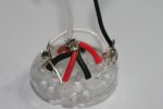
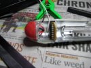
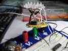
Here are a few photos, you will be able to tell I am not an expert with a solder gun:

IMG_3672.jpg
IMG_0537.jpg

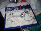
A bread board is a requirement if you are going to play with electronics along with a lab power supply. I got a good one off of ebay for $30, and my local electronics store wanted $100 for a power supply. I like having a power supply because I can set the voltage to be whatever I need it to be.

IMG_0543.jpg

Sorry for the fuzzy picture!!

IMG_0544.jpg

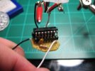
A test fit to see if it will work. I didn't take into account the socket for the chip, so it was a VERY tight fit.

IMG_0547.jpg

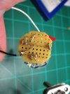
My first perf board solder!!

IMG_0546.jpg

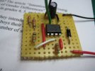
Circuit board from the top

IMG_0545.jpg

The assembled circuit. It is a tight fit, and currently I do not have photos to show of it, but I do have a few videos. No time to post them tonight, I will get them posted soon.

More updates as time allows.
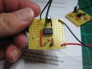
 
Looks like an ambitious build up.
Almost makes me want to go back and finish mine
 
Here is a video of the circuit in action:

[youtube]http://www.youtube.com/watch?v=ccjpBJKnr4A[/youtube]

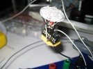
When I built the second one, for the other nacelle, I decided to do away with the socket for the IC chip. I originally used the socket because I had read that these chips are sensitive to heat. I was not sure of my soldering skills, so I went on the side of caution. For the second one, I came to my senses, and just tried one without the socket. (These chips are pretty cheap on Ebay. I paid about $9 for 25 of them.) So if I burned one up, I wasn't wasting too much money. That risk paid off and I now have a much smaller circuit :D :

IMG_0567.jpg

My next step is to re-build the other one without the socket, the fit is soo much better.

Parts list for the circuit:
  • MC14060B 4060 CD4060B Counter 14 Bit CMOS
  • One 0.01 micro farad capacitor, mine says 103f on it
  • One 47000 Ohm resistor, or 47K resistor
  • six 3 mm leds, white

The circuit works by alternating the current through a set of three leds. In other words, when the current is going in one direction, three leds light up, when the current reverses, the other three light up. (Led's are polarized, they only work when a current is passing through in one direction. When current tries to go the other way, they don't work. This is why you have to be careful when you set up a circuit.)

Now that I have that done, I can start to work on the other lighting systems. The lighting circuits are my priority. Some of the assembly on this model will be very easy, so I work the easy part on evenings when I do not have a lot of time.

Speaking of which, here are a couple of photos of my light test with the reflective paint:
IMG_3702.jpg
IMG_3709.jpg

Lighting is done with a 5 mW laser. If the surface is not very reflective, the light will not show up in the photos very well. In other words if the surface is adsorbing the light, it won't shine. Since it is lighting up like a Christmas tree, I feel like that paint is doing a good job.
 
I did make a few plans before I started the model. I made a lighting plan, a painting plan, and an assembly plan.


Here is the lighting plan:

First decide upon a voltage. The led's require a resistance so that they do not get too much power. With a voltage over their limit, they burn out. I decided to go with 9V

Nacelles: Spinner circuit. That is done
Navigation lights: Those are the red and green blinking lights. That circuit is also done, I have two choices here. A 555 timer, or a variation of the nacelle spinner.
Position lights: These are the white strobing lights. On the NX, these are not extremely bright. I am going to try for a variation of the spinner circuit
Steady on lights: Easy, no circuit needed, just a resistor

For the navigation lights, I will probably go with the variation of the nacelle spinner. The 4060 chip is not power hungry, and if I do this correctly, I might be able to power the whole thing with a 9V battery. In addition, both the 555 timer and the 4060 will operate at 9 volts. I have the high voltage variation of the 4060, which will operate with anything between 5V and 15V. For more information about the chip:

http://electroschematics.com/4060/ic-4060-design-note/

The 555 timer operate between 4.5V and 18V, but from my readings is a "noisy" chip and will introduce random signals into the circuit. It is also not very suited for use with CMOS type chips and the 4060 is a CMOS chip. Because of this, I am going to try and avoid the use of a 555. So my next task in this area is to get the navigation and the position circuits working. Once those are done, I have only steady state lights to wire, but this is easy, it will be tedious, mainly because of all the resistors I will have to soldier in.

I want run all of the navigation lights off of the same circuit. The down side is that I will have to run wires from the nacelles to the saucer section. This is a large model, so space won't be an issue here.

For the position lights, since they are not bright like they are on the refit, I am going to try them with fiber optics. In the show, they are smaller than the navigation lights. This is my main motivation for trying with fiber optics. The smallest led I have is 3 mm. I know that they are made in smaller sizes, but I don't know if I want to try and work with them. I have a few very bright led's, and if I use one of these in the circuit, I might be able to pull this off. I also have fiber optics in various sizes from 0.5 mm to 2.5 mm. This will allow me to find the perfect fit.

I will also use fiber optics in other parts of this build. There are a lot of smaller lights scattered through out the model. Bordering the shuttle pod bay, on the front near the main name plate, for just a few examples. In the show, I noticed that in the front of the saucer section, the name is lit up pretty well, I don't know if I will be able to replicate that. We will see if I make it work.

For the painting plan, I am still working on it. The recommended colors, don't really match the show, and I have been thinking about how I want to approach this. The colors used on TV have a golden hue to them, and the recommended colors are all black and silver. For the aztecing, I have purchased painting mask from aztec dummy. I got them through Don's light and magic. I hope to get this far within the next week or two, I have eight days away from work starting Friday. The nacelles worry me here, they will require a lot of filling, and the lighting has to be done before I can start painting. This is why I have started with the lights. If I go with mixed paints, I want to shoot the paint all in one go. This means that the nacelles must be done before I can think about more than light block paint.

Assembly plan: The first thing I did was read the instructions. They are horrible for this kit. Small print, not listing all parts, they also came with a correction sheet. I then promptly ignored them. They call for painting before some assembly, I want to do as much assembly as I can before I paint. There are a few tricky spots in this kit, and I will go into more detail on this and the assembly plan in the next post.
 
This is an awesome project! I'm going to go back and read all the stuff your wrote again to learn more stuff!! :) Definitely put this model on my list.
 
This is awesome. You've made a lot of progress on this so far and the lighting scheme is really cool. When reading about the seams on the nacelles it reminded me of an article I just read on the new Vulcan shuttle Surak. http://www.round2models.com/workbench/vulcan-shuttle. The article describes a technique for seam filling from the inside out using liquid solvent glue to soften the joint just a bit and then squeezing it tight while it's drying just enough to squeeze out some of the melted plastic. This fills the seam and just needs a little scraping/sanding to clean it off. See the description in the article and figure 4.

I've never tried this but if it works cleanly on your parts it might allow you to get by without adding putty to fill the seam.

Looking forward to more progress!!

-Doug
 
Doug,

Thank you for the link, I have that model and there is some useful information there. I have used the thin cement technique before. I will probably use it here too. The one thing that worries me is the textures on the part. I will try to use a triangular file to sand once I get the parts glued together.

Back to the assembly plan:

When I took a look at the directions, the order of assembly was not suited for lighting. This is the order I decided upon:
  • Nacelles
  • Secondary assembly, add on parts, greeblies if you will.
  • Saucer section, and the engineering hull
  • assembly the upper and lower halfs
  • Nacelles to pylons

The reason I wanted to start with the nacelles is that I am most worried about the seams, and the circuits for lighting at the time seemed the most challenging.

Here is a photo of the seam that worries me the most:
nacelles.jpg

I plan on evening out the ends of those two prongs, and then using a cut out from thin styrene to fill in the small triangular recesses. This will hide that joint nicely. I am also thinking of sanding off the rectangular raised portions and replacing them with styrene cutouts.

The second concern is the connection of the nacelles to the pylons. From reading on other sites, this is a big one. Most models have trouble with "nacelle droop" There are almost no connection points between the pylons and the nacelles, you can see this in the below photo:

pylon.jpg

I have to cut a few holes for wires, and fiber optics in these supports and I may try to reinforce with some steel rod I bought at the local RC shop.

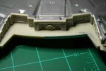
Another of my concerns is the structure of this model. A few of the joints look weak to me like the following joint:

saucer-joint.jpg

This is the joint that connects the engineering hull to the saucer section. I think the weakness in this joint is why the stand has three support rods. Some of you more experienced modelers out there might be able to tell me if it is going to be a strong enough joint to support the nacelles and the engineering hull if I do away with the secondary stand rods. I would like to have one brass rod support the model instead of three. (I did purchase brass rods in the same diameter as the support stands just in case I want to go that route. I might try to reinforce this joint with a laminate of steel rods and styrene.

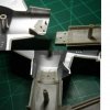
The joint where the pylons attach to the engineering hull looks pretty strong. It has a couple of keys on it, and the pins look pretty strong. Here is a photo of this joint:

pylons.jpg

I am a little more concerned with getting all of the wiring routed through that joint than I am with its strength.

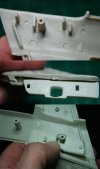
Here is a photo of some of the preliminary work:

work.jpg

In the top part of the photos, I have drilled a few holes for fiber optics. The model has a shroud that goes over this part, and the shroud had a few points on it that were lighted in the TV show. The directions call for paint only. The fiber will be in place before painting begins.

Here is what happens when you don't plan ahead:

mistake.jpg

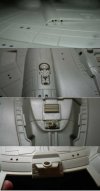
I was doing some of the preliminary assembly work, and got ahead of myself. This dome is suppose to be lighted. I have already glued together a small deck, with walls on top of the deck:

rear-deck.jpg

I don't think I am going to attempt to fix this. I had already planned on blacking out a few windows in the hull to give it a lived in look, so this will be one of those windows.
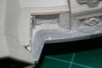
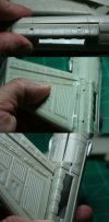
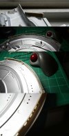
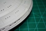
My other major concern is the windows on the rim of the saucer section. This is an old model and some of them have warped. This has already caused a few problems with earlier assembly. The photo shows some of this warp:

saucer-rim.jpg

The top part of this photo shows one of the problems I have had. This part when put in place with the keys on the saucer section did not line up with the upper saucer section when the two haves were placed together. I pulled up the part and re-glued it down making sure of the alignment on the second try.

If I am careful with putting these parts together, I shouldn't have too much trouble. The problem I am worried about is light leak. There is a lot of little seams here and I don't want to do a paint job until they are put together.

After these things are done, I might scratch build a shuttlepod bay. I have a good photo for reference, and I got these off of Starship modeler:

shuttlepod.jpg

I have brass rods for the shuttle pod support and the bay wouldn't have to be too detailed, because of the viewing angle, and the size of the bay. It will be my first attempt at a scratch build.

And the last part of the assembly is the stand. I want to build a new stand and practice my wood working skills. Here is a photo of the original stand:

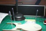
stand.jpg

From my research on other sites, these three plastic rods are not strong enough to support this model. I would like to incorporate the plastic base somehow, maybe as a platform for the on switch. Or a shadow on the base of the model above.

Tomorrow night, I should be able to get all of the circuits done. This will leave me with just putting resistors on leds for a couple of hours.
 
You have a lot more patience for this than I did with mine.
You may actually finish this. Mine's still sitting waiting for decals after almost five years.
 
I learned a long time ago, that the best way to approach a big project is to set yourself a lot of small goals. This way, you do not get frustrated when things don't get done fast. So each week, I set a goal, and work on getting it done. To me the worse part of this project is the lighting, mainly since I knew so little of it going in. I have the navigation light circuit done, and mostly built. I just have to get the timing right, so it looks much like what you see on TV. The circuit for the position lights was giving me fits tonight, but I finally got it to work. I couldn't figure out how to get a 4060 chip to strobe correctly, but I did get a 555 chip to strobe. Way too late to go into details, that will have to wait until another day. But, the hard part of the lighting is done for me. The rest is soldering and wiring. I don't mind that as much as trying to decode electronics websites. The happy thought :D to this is that when I go to build any other star trek model, I have the lighting figured out for all of them. I will post my circuits later.
 
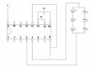
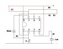
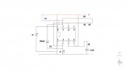
I have finished putting together the circuits for the blinking lights. This first image shows the Circuit diagram for the Nacelle spinner circuit.

Nacelle-spinner.jpg

This circuit works by sending an alternating current through the two sets of LED's. When the current runs in one direction, three light up, when the current reverses, the other three light up.

R1 in the picture is a 47K resistor
C1 is a 0.01 micro farad capacitor. The label on it states 103f
The chip itself is a MC14060B 4060 CD4060B Counter 14 Bit CMOS

If you don't know how to read a circuit diagram, use this link. It explains what the symbols mean: http://www.kpsec.freeuk.com/symbol.htm


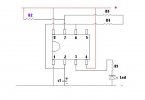
For the navigation lights (The slow red and green blinking lights) , this is the circuit I used. It is based upon a 555 timing chip:

555-navigation.jpg

R1 is a resistor so that your LED does not burn out. The 555 chip does not reduce voltage across its output terminals. So if you use 9V, the LED would see 9V. This is not good if you are an LED that wants only 3.2 V. So this resistor dependent upon the voltage of your LED. You can use this link to find out what resistance to use: http://led.linear1.org/led.wiz
R2 is a 1K resistor. This resistor is not that important, but is must be much smaller than R4.
R4 can be one resistor, or many in series. This is the resistor that controls blink rate. By watching the show, I figured I needed a 160K resistor in this spot. (I sat my circuit down in front of the TV, used a variable resistor, until I hit the same timing as the show. Then I measured the resistance,) I did not have a 160K resistor in stock, so I used two resistors in series. Resistors in series add, so I grabbed a 100K resistor, and a 68K resistor. Came out pretty close to what I wanted.

C1 is a 63 volt, 10 microfarad capacitor, polarized Electrolytic (a 25V version works too!)

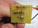
Here are photos of the completed circuit:
navigation-front.jpg
navigation-back.jpg

As you can see in the photos, my soldering skills are not the best, but they got the job done.

Here is a diagram of the strobe circuit, It is based upon a 555 timing chip

555-strobe.jpg

R1 is known for this circuit, since I am using a very bright white LED, its value came out to be 320 Ohms. I didn't have one of those on hand, so I used 330 ohm resistor, you should round the values up if you don't have exactly the resistance you need. This way the LED does not see too much voltage.
Both R2's are 10K resistors. The R2 in purple controls the duration of the blink. The larger this value, the shorter the blink is.
R3, and R4 could be replaced by one resistor. I didn't have a 140K resistor on hand, so I had to use two 20K resistors in series with a 100K resistor. I used the same method mentioned above to find the value of this resistor. This combination of resistance controls the time between blinks. The larger this resistance, the longer the time between the two blinks.
C1 is a 63 volt, 10 microfarad capacitor, polarized Electrolytic (a 25V version works too!)
This circuit also has a diode in it. They are rated by voltage and current. The strip on the diode has to go on the end that is negative. In a circuit diagram, the arrow points to the end that is negative, so in my diagram the arrow is pointing down, so the strip would go on the bottom. My diode has IN400 printed on them.

Here are a few photos of the circuit:
strobe-front.jpg
strobe-back.jpg

I had to go with the 555 timer chip for a reason, I couldn't get the 4060 to blink the way I wanted it to. The 4060 is a much easier chip to work with, and has a lot of positive values going for it. But I just couldn't get it to do what I wanted. Here is a video showing the differences between the two chips as far as models are concerned. I do not know a thing about the inner workings, or how they actually work. I only know enough to get my circuits running the way I wanted them to. I am still learning about electronics. It is a very slow process.

[youtube]http://www.youtube.com/watch?v=_bTthSf_8P0[/youtube]

Now that these three circuits are done, I can start working on the nacelles and the lighting for the warp coils. Once I get that figured out, I can actually start to work on building the model. The only lighting left is the joy of soldering many resistors to LED's for window lighting. It is easy work, but time consuming. Nothing like figuring out these circuits. I also have to figure out how I am going to route the power, but again that is much easier than figuring out the above.

Why did I do this? There are lighting kits for this model available. One of them is somewhat reasonable too. (I think it is around $69 U.S.) One this is cheaper. Total cost for the parts should be around $20. Second, I now have the knowledge to build more circuits like this. I have quite a few star trek models sitting in a pile waiting for attention. Most of them have lighting that would require these circuits. A lighting kit for each one of them would cost way too much.
 
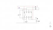
Just on a whim, I decided to power up all of the circuits on the same power supply to see what they looked like. Sort of a test run if you will. I did plan on letting everything run for 7 or 8 hours once I get all of the electronics done. Just to make sure I don't have any burn outs before I seal everything up. Well I got a surprise. If you read up near the top, you will see that I posted that the 555 had problems with noise. In other words, the chip emits signals into the power supply. When I powered up the three different circuits they did not behave the same way they did when they are set up separately. This noise was even affecting the 4060 chips I was using for the nacelles. I spent a couple of hours tonight trying to figure out how to fix this. I found the answer on two different sites, but since they were in electronics language it took a while to interpret. Below is the new revised circuit diagrams:

This one is for the navigation circuit, or the green and red blinking lights:

555-navigation%20update.jpg

And this one is for the position lights, or the white lights that strobe:

555-strobe%20update.jpg

In both circuits I had to add a capacitor across pins 1 and 8. This is c2 in the diagrams. This capacitor is a 100 micro farad electrolytic capacitor, the voltage on the capacitor does not matter as long as it is larger than the voltage in the circuit. I am using a 50V capacitor. The positive poll goes on pin 1, the negative on pin 8. (The negative pin has a stripe on the capacitor, and also has the shorter lead, just like an LED.) This fixed the issue and now when I power up all the circuits at one time, the behave just like they do when powered alone. With this done, I turned to lighting the nacelles.

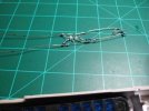
The below photo shows the light strip I made up. This is a work in progress and not the finished product.

light-string.jpg

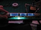
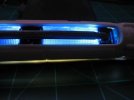
Using LED's can be troublesome due to hot spots. The NX has black spots on the nacelles, and I set the spacing such that the LED's fall in these black spots. It tones them down some, but not completely. I could have use cold cathode lighting for this, but they produce heat. LED's do not produce anywhere near as much heat, and last much longer. Here are a few photos of the work in progress:

outside.jpg

inside.jpg

And a photo showing some of the light leak I have to take care of either before assembly or after. Sorry for the fuzzy photo, I was too lazy to get out the tripod or the good camera:

light-leak.jpg

With this circuit done, I need to string the fiber optics, and then I can work on sealing up the nacelles and filling seams.
 
Thanks guys!! Do you think I should do a few tutorials about lighting? From the research I have done, there is very little out there about lighting models that is useful to the beginner.
 
Well, I didn't get a whole lot done this week. Work is starting to pick up, and will keep me very busy over the next six weeks. In addition, I have taken on a project that will take up a lot of my time in the next 5 or 6 weeks. So progress will be slower than it has in the past. I am trying pretty hard to get this thing where I can paint is soon. Once painting is done, I will be able to start on lighting the saucer.

I let the circuits for the nacelles run for about 10 hours, just to make sure I didn't have any faulty LED's. Everything came through with no burnouts, so the circuits are ready to be installed.

I spent a couple of days patching up light leaks. Some of them required a new coat of rattle can paint, the same paint I have been using in the past. I put a coat of this paint on the nacelles and I want to let them sit and cure up a bit before I start to install the lighting.

While reading about another lighted model, I came across this product:

http://www.shurtape.com/tabid/79/default.aspx?ProductID=3&DisplayType=1&Level1=15&Level2=16

It is basically aluminum foil with a stick backing. It does wonders for light leak, and is just as reflective as the paint I have been using. An added bonus is that you don't have to mask the model before painting, just apply the tape, trim if needed, and you are set to go. One draw back is that the tape is thicker than paint, so I won't use it where clearance is important. Here is a photo of some of my work:

foil-tape.jpg

In addition, I have been working on the saucer section. There was one major spot of fill work, here is a work in progress shot:

saucer-fill.jpg

The silver paint is to highlight any mistakes in the fill. I can usually find these spots by feel, but the paint helps to highlight anything I cannot feel. It still needs a bit of work. I usually do a little fill, let is sit 24 hours, then sand, or file down. Repeat until done.

I also did some work on the rim of the saucer section:

saucer-done.jpg

These pieces were pretty warped. I considered using CA to glue them together, but decided against this. CA does bond quickly with little hold time, but I was pretty sure I would need to reposition these pieces as they set in place. CA would bond to quickly for this to be practical. I tried gluing one end, letting it cure and then gluing the other end. I am using Tamiya extra thin cement, and discovered a neat trick. I would glue down the whole part. Hold in place for 10 to 15 minutes. Once they were set up, a second application of the thin cement, would loosen the bond, and allow me to move it to position. Hold in place for another 15 minutes, and then I could work on the other end. Some of these parts needed to be moved 7 or 8 times to get them set just right. There are 12 of these pieces around the rim of the saucer, so you can imagine that this took quite a bit of time. Let the parts sit too long however, and the second application of thin cement does't move them easily. I tried clamping these pieces, but they are too irregular for this to work. I had to hold them by hand, because the clamps were distorting the position of the pieces.

There are still a few gaps that need to be filled, and I have to apply light block to all of them. I will probably use thin strips of styrene to fill these gaps. Not sure about that, I need to put some in and see how it looks, I will report on this when I am done experimenting.
 

Latest posts

Back
Top