Medium Tank T6

Scale Model Addict - Model Tips, Guides, Tools & Tech, Tutorials, and Community

Help Support Scale Model Addict:

Jakko

Well-Known Member
Joined
Oct 9, 2024
Messages
2,383
City & State/Province
Netherlands
With the K2 Black Panther almost finished and other models that mainly need painting, this will be my next model:
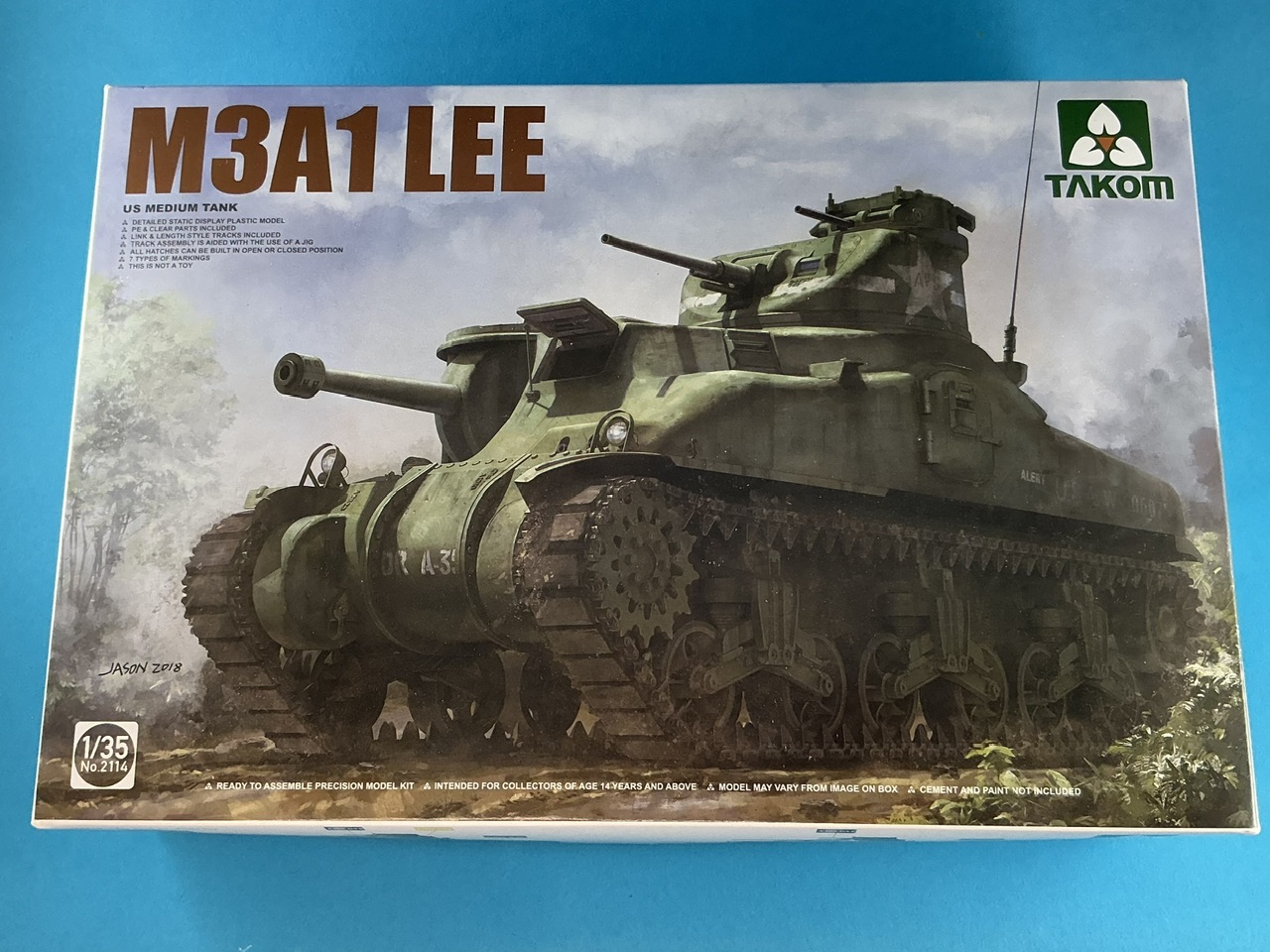
IMG_3861.jpeg


Well, not quite as it's shown on the front of the box. I have a few extra parts for it:
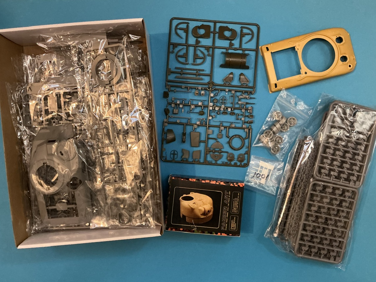
IMG_3863.jpeg


;)

From all of this, and probably some more stuff from my spares box, it will become:
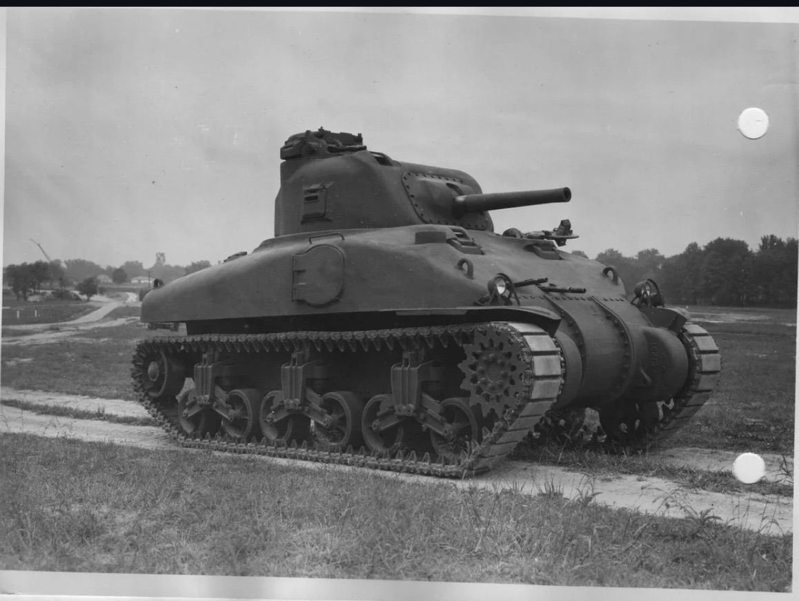
IMG_3864.jpeg


The prototype of the M4 Sherman, in its earliest incarnation as pictured above. Later, the machine-gun turret was removed and counterweights added to the main gun barrel:
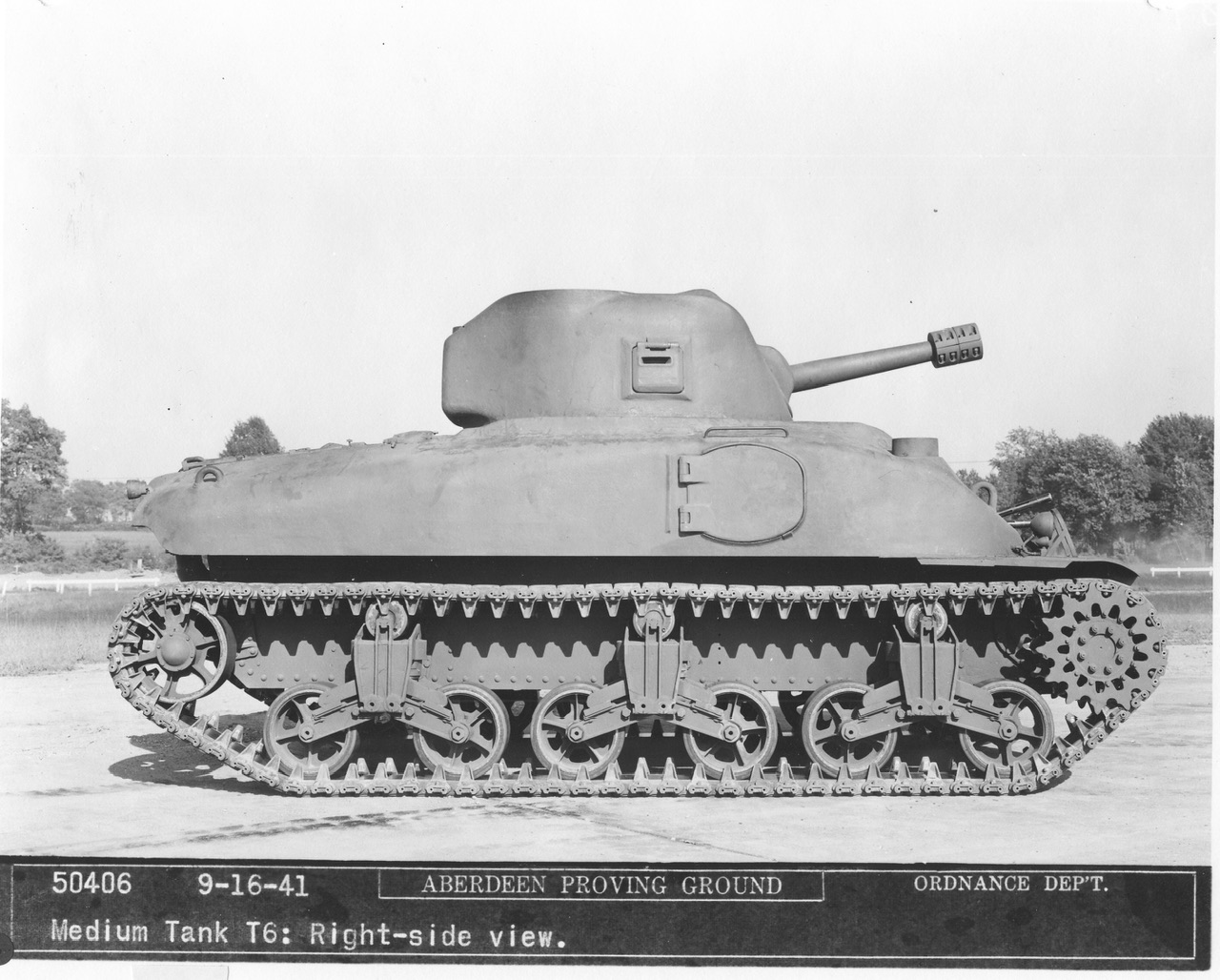
IMG_3791.jpeg


For those who want the full story of the T6, the Sherman Minutia Website has you covered :)

I've had the idea for a number of years to build this one, but didn't get round to it until now. It started when I bought Panzer Art's very early Sherman turret for cheap, and soon decided it would be most interesting to build the very earliest Sherman with it (there are other choices, even a tank photographed in action in Italy). Originally, the plan was to use an M3 medium kit from MiniArt, with an M4A1 upper hull from Asuka, but last year I realised it would probably be easier to use a Takom M3A1 instead. The rear part of the T6 hull is very similar to that of the M3A1, while the M4A1's is a further development of that. So now, I intend to cut the back off both and stick the Asuka front (everything before the engine deck) to the (modified) Takom hull from the front of the engine deck back.

In addition, I've got a sprue for some parts I couldn't find in my Sherman spares box, ordered direct from Asuka in Japan together with the upper hull, a set of T41 tracks from MiniArt, roadwheels from MiniArt as well (I don't think Takom's are very good) and a set of .30-calibre Browning barrels, because some of the machine guns on the T6 had cooling jackets with slots in rather than circular holes.

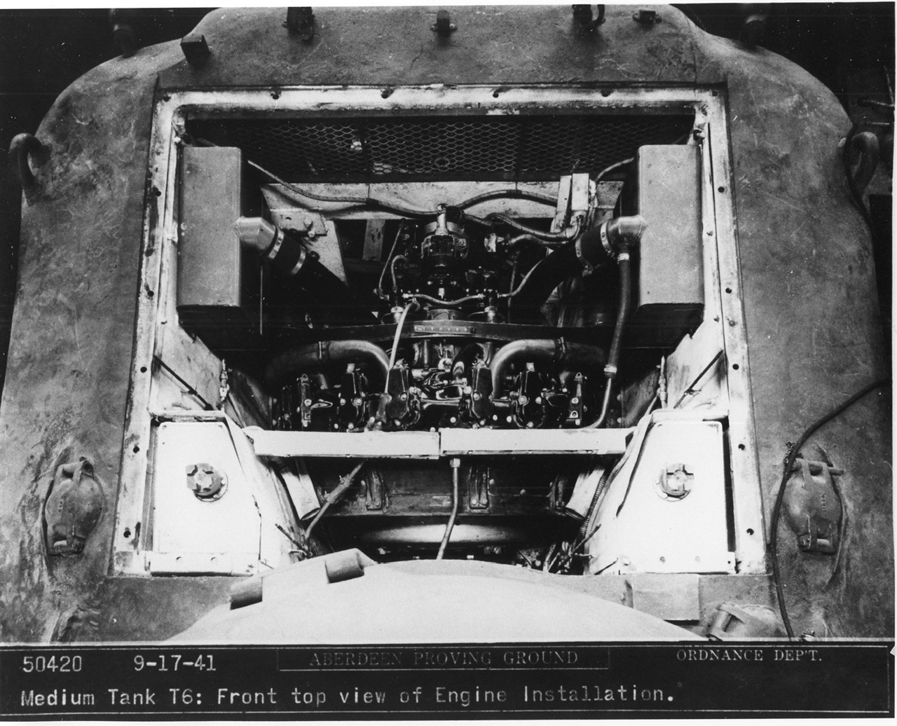
For references, I have a lot of photos of the real T6:
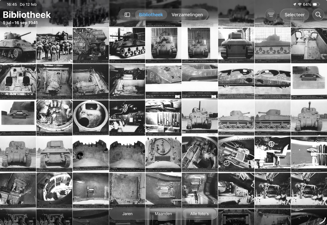
T6.jpeg


This is about three quarters of them, the rest didn't fit on-screen :) Many of those photos you will also find online if you search for pictures of the T6, but this lot also includes some you don't normally see.
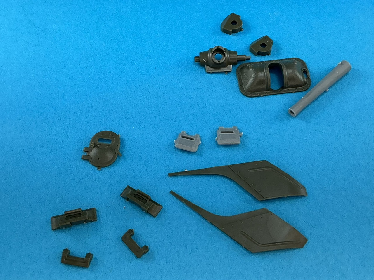
 
Before starting construction, I went and looked through my Sherman spares boxes. This is what came out:

IMG_3871.jpeg


At the front are direct vision blocks with flaps as well as mudguards of the correct style for the T6, above them are a driver's hatch and two pistol port flaps from an M3 medium tank. At top right are the parts for an M34 gun shield (except the moveable shield that attached to the gun) and an M2 75 mm gun barrel. The grey parts are MiniArt, the rest is Asuka.

I think I know why the Panzer Art turret was on sale:

IMG_3867.jpeg


It includes an M34A1 gun shield, but the moveable shield is the one for the M34. An M34A1 is far too late for this very early turret, but it also turns out that the hole in the turret is too narrow for the Asuka M34 shield … An M34A1 from a Dragon kit, that I also found in my spares box, does fit, which makes me think Panzer Art modified a Dragon turret for this conversion set :) Oh, well, I'll need to enlarge the hole, then. Could be worse :)

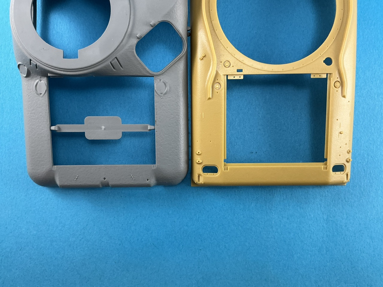
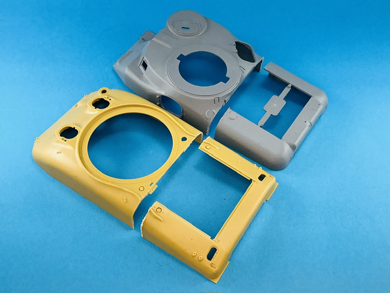
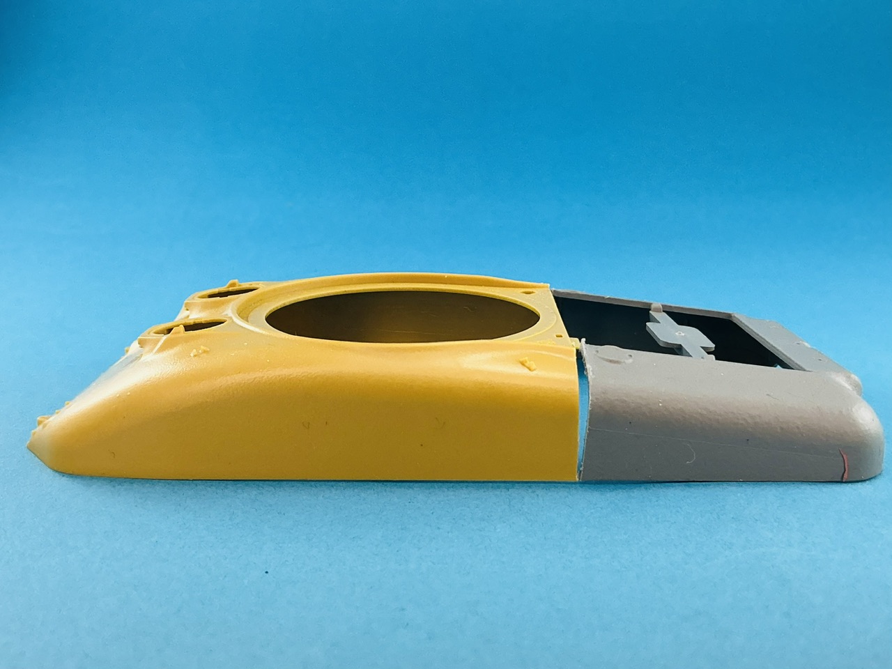
Here's a comparison of the hulls:

IMG_3868.jpeg
IMG_3803.jpeg


As I already mentioned, my first plan was to modify the M4A1 hull (yellow) but the T6 had a back end very similar to the M3A1's: more rounded corners and that projecting part behind the opening for the engine deck. It'll be easier to do a transplant.

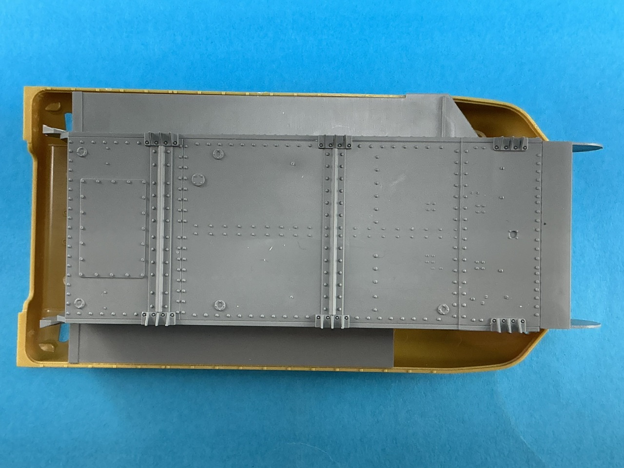
The Asuka upper hull fits the Takom lower quite nicely:

IMG_3869.jpeg


On the right-hand side (at the top in the photo) it may not look like it, but that's because there's a small projection on the lower hull, since this is where the 75 mm gun sits on the M3. By removing that, the two should fit fine (he said … ;) ).

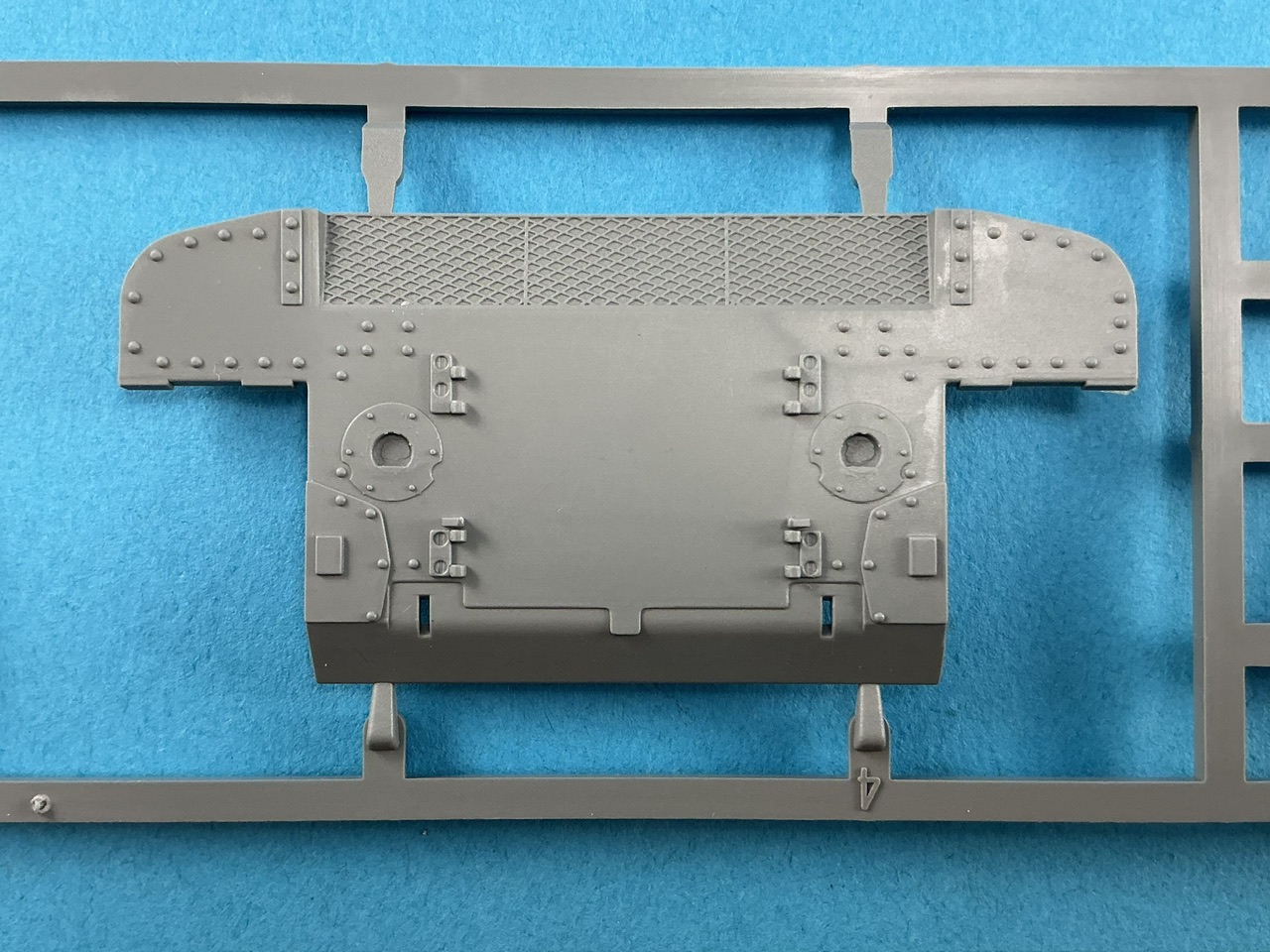
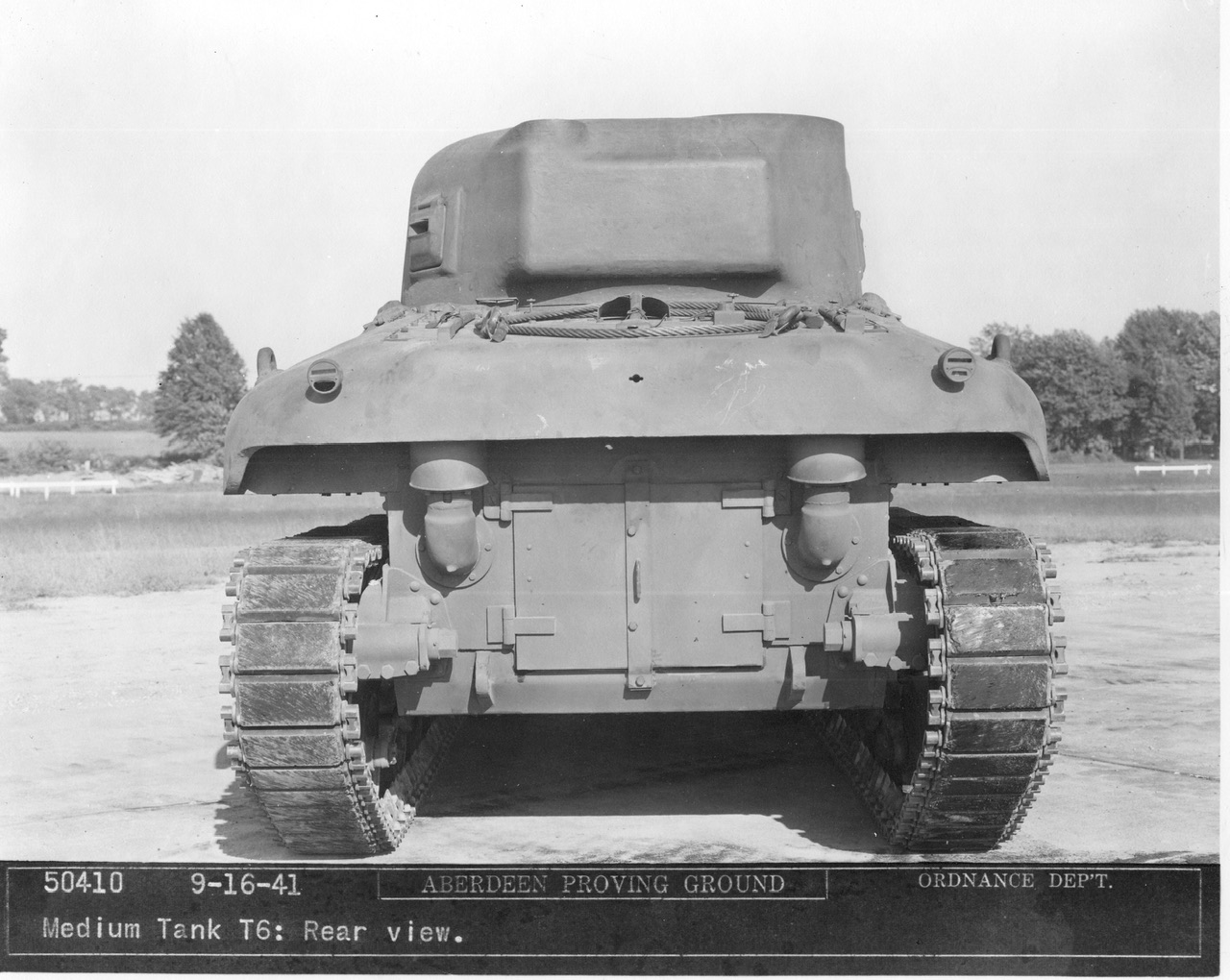
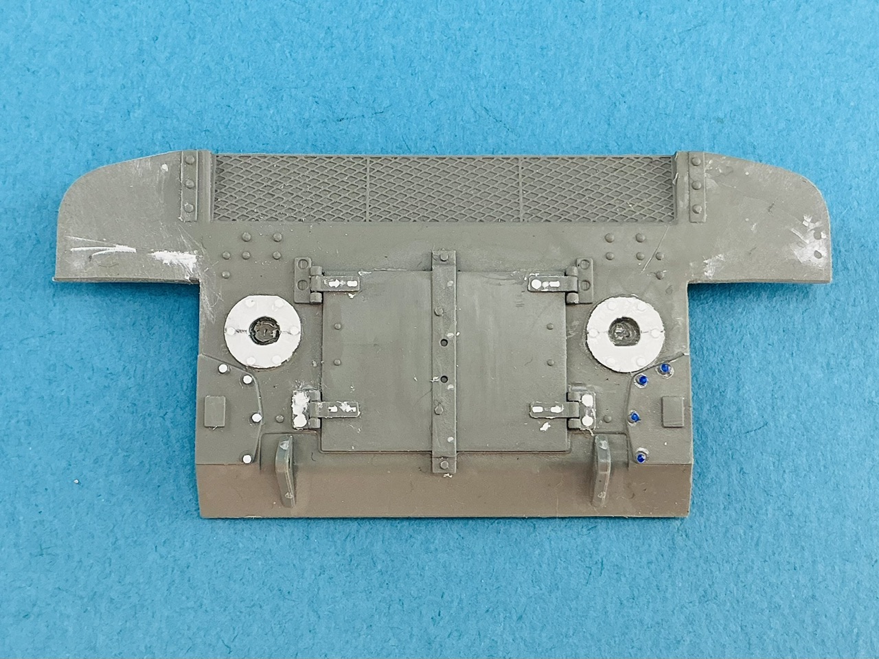
The hull rear plate has details that I had hoped weren't there:

IMG_3870.jpeg
IMG_3798.jpeg


It's a small thing, but the round plates that the exhaust pipes come out of, have two little notches on the Takom part while the T6's were completely circular. Both are possible on M3s, but it does mean I'll have to change it. I also think the rivets look too small, so I might replace those too.
 
I started construction with the rear plate of the hull, because that needs to be in place to locate the upper hull correctly.

IMG_3892.jpeg


After removing the bolts on the round plates and the rivets next to them, I punched two 7 mm discs from thin plastic card and glued them on the moulded-on plates. After the glue dried I cut out the opening in the middle for the exhaust pipes (just stick a knife blade in, cut to find the edge and follow that) and added bolts made with a hex punch-and-die set. I also used a domed punch to make slightly bigger rivets for the plates that the idler mounts will go on to later.

At the upper left and right were rivet heads, but I cut those away because the photos of the prototype don't show them, then filled the scars with putty. I also used that to fill the screw heads on the hinges for the engine hatches, except the upper ones on the rear plate itself: the photo of the real T6 shows they were present on those (on the M3, these hinges had holes drilled for these screws, but many were welded on through those holes instead).

I also removed a triangular plate on each side of the doors, which was a stop to prevent them from opening which the T6 didn't have, and four rivets on the vertical strip over the two doors, because it was welded on the T6.

Altogether a lot more work than you would expect for a simple rear plate :)

Then on to the upper hull:

IMG_3893.jpeg


I just sawed through both as square as I could, level with the forward edge of the opening for the engine deck. The hardest of the four cuts was on the left of the M3A1, and I ended up angling to the left too far there:

IMG_3894.jpeg


But that's no real issue, I'll take a bit off that later so they join properly.

The hull front of the T6 was different than the M4A1's. First of all, the headlights weren't on there but on the mudguards, and the hump above the machine-gun mount also wasn't present. Out with the file!

IMG_3895.jpeg


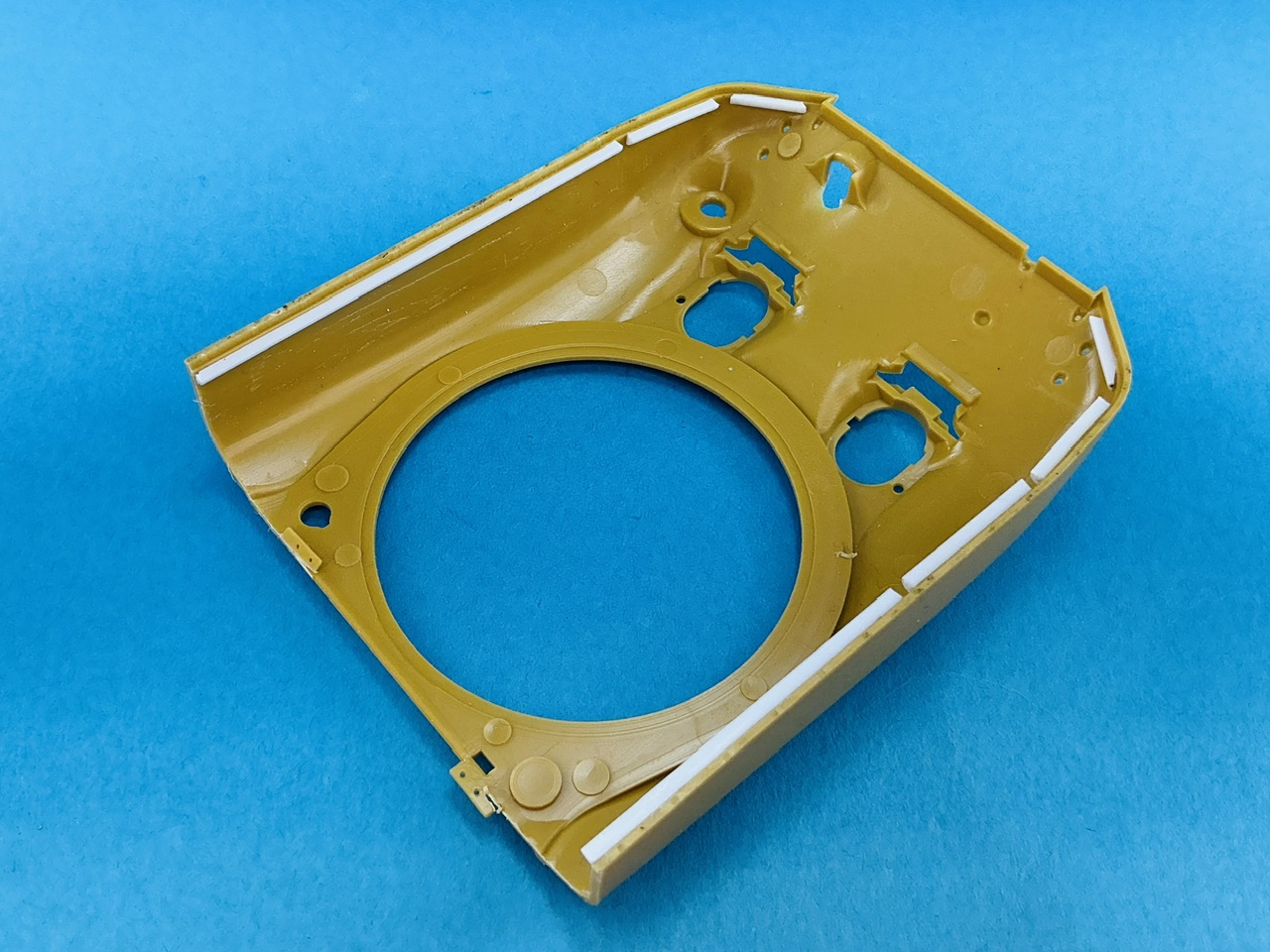
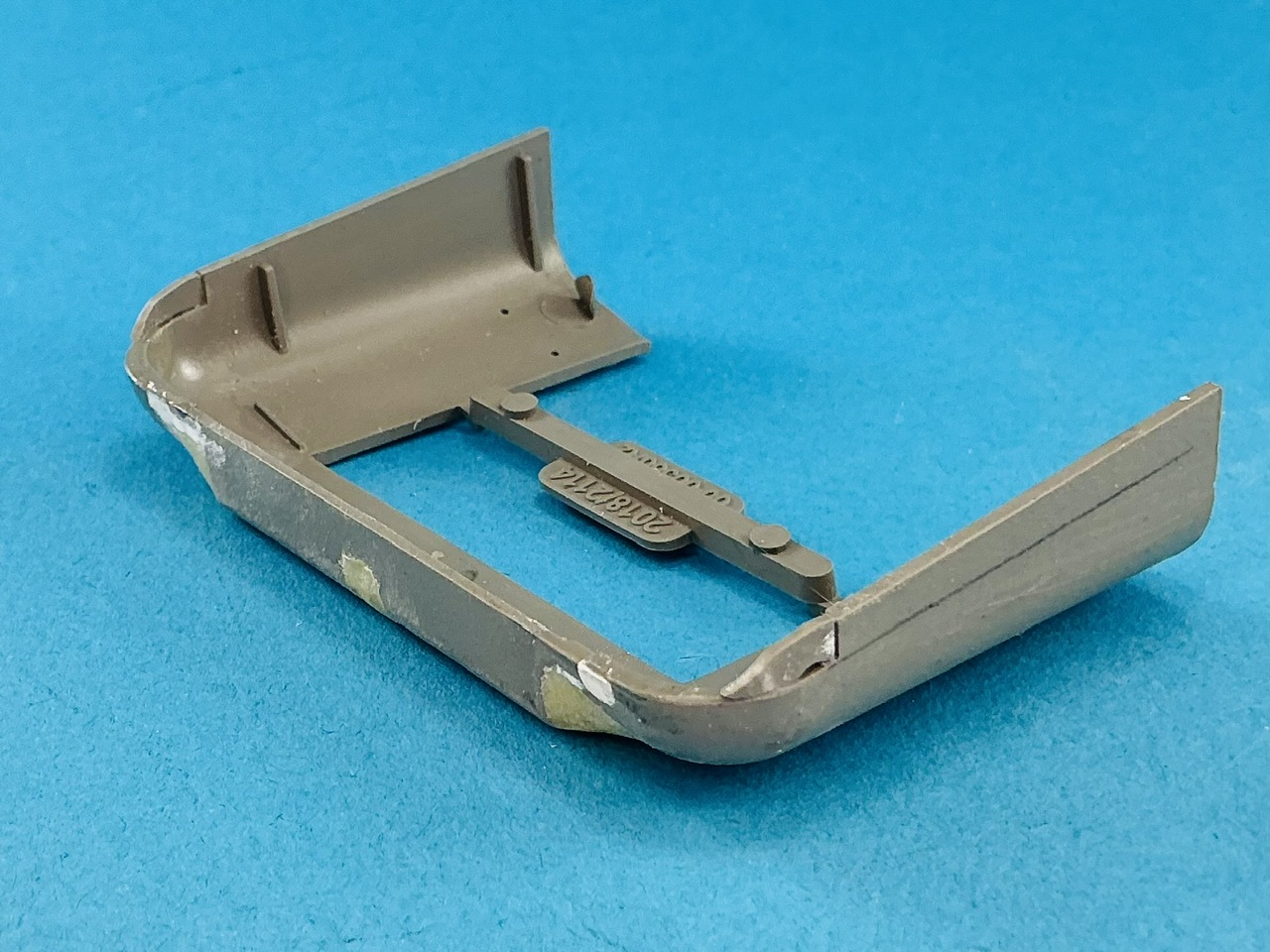
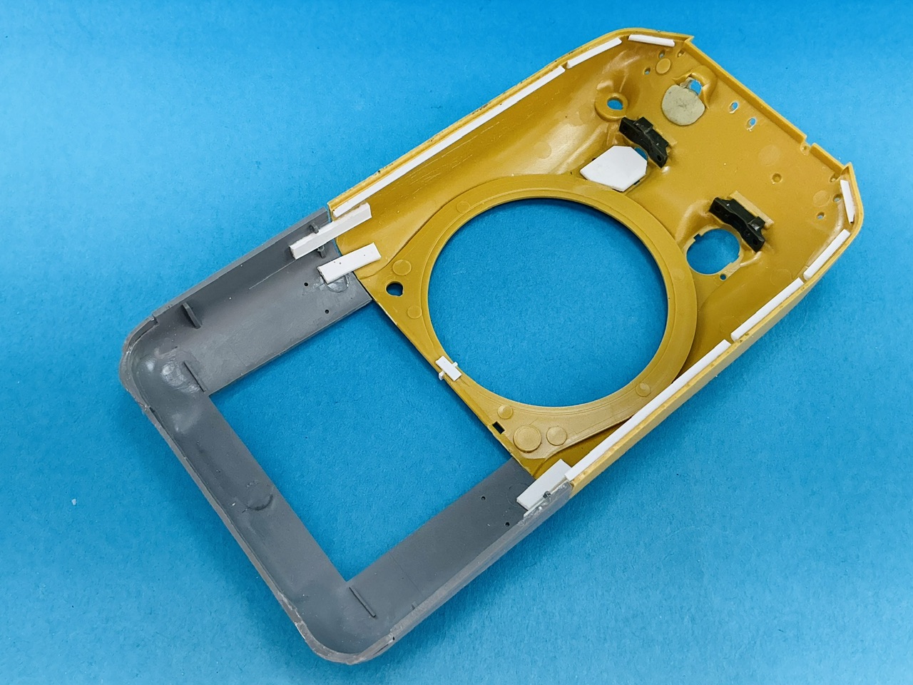
On the inside of the Asuka hull, I glued plastic strip:

IMG_3896.jpeg


The thicknesses of the walls is about the same on the two upper hulls, but Asuka's narrows at the bottom to fall over the sponson floors. This means it doesn't fit properly on the Takom lower hulls, because that's sized for the Takom upper hull that doesn't narrow, but with these strips the Asuka hull can't fall over the Takom sponson floors, and they'll make it easier to add the forward floor sections later on from plastic card.

Let's put them together for the moment:

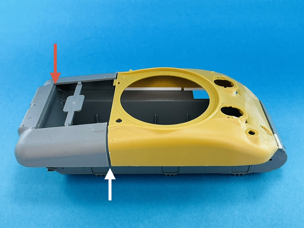
IMG_3897.jpeg


Because I accidentally cut the left-hand side at an angle, it indeed doesn't fit properly — see gap at the white arrow. The Asuka hull sits where it should, but the Takom part is too far back as a result. At the red arrow, you can see the upper edge of the rear wall, which should be level with the rear edge of the engine deck opening, instead of slightly forward of it as it is here.
 
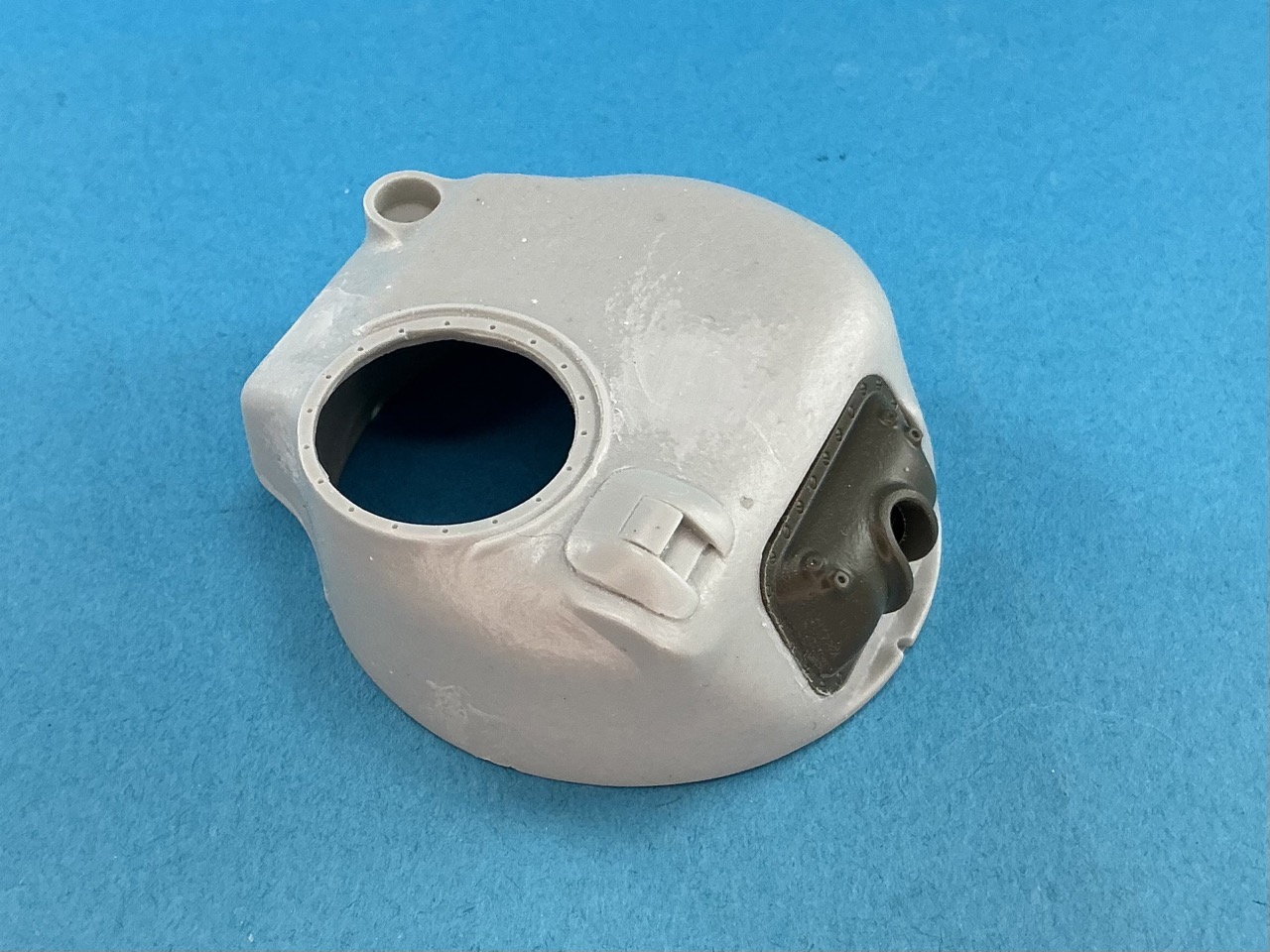
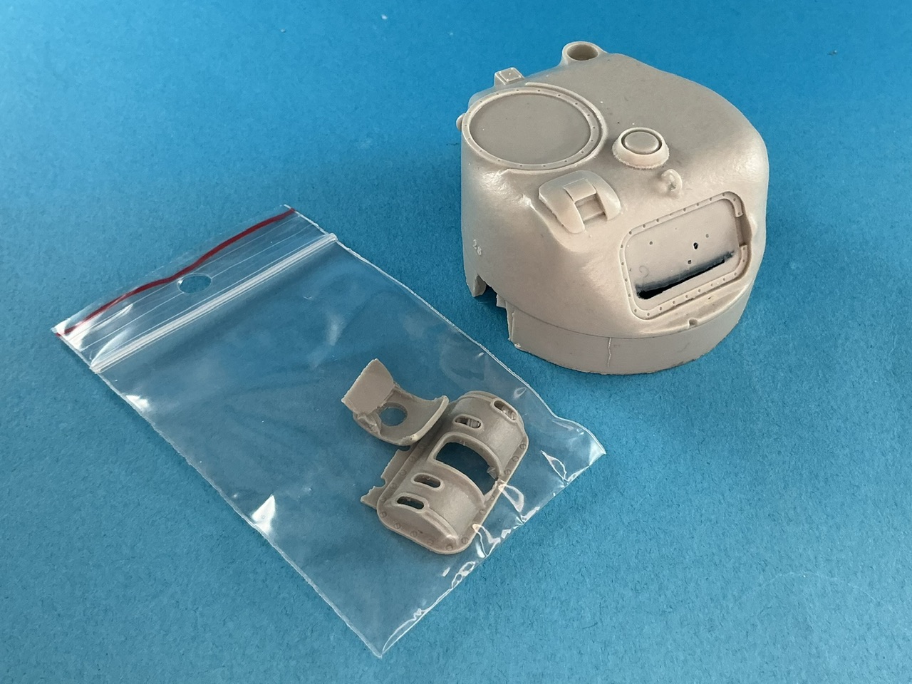
The Panzer Art turret is a good representation of a very early M4 turret, but unfortunately that means it has all kinds of stuff on it that wasn't on the T6's turret. This is easy enough to solve with a saw and some hobby knives:
IMG_3909.jpeg


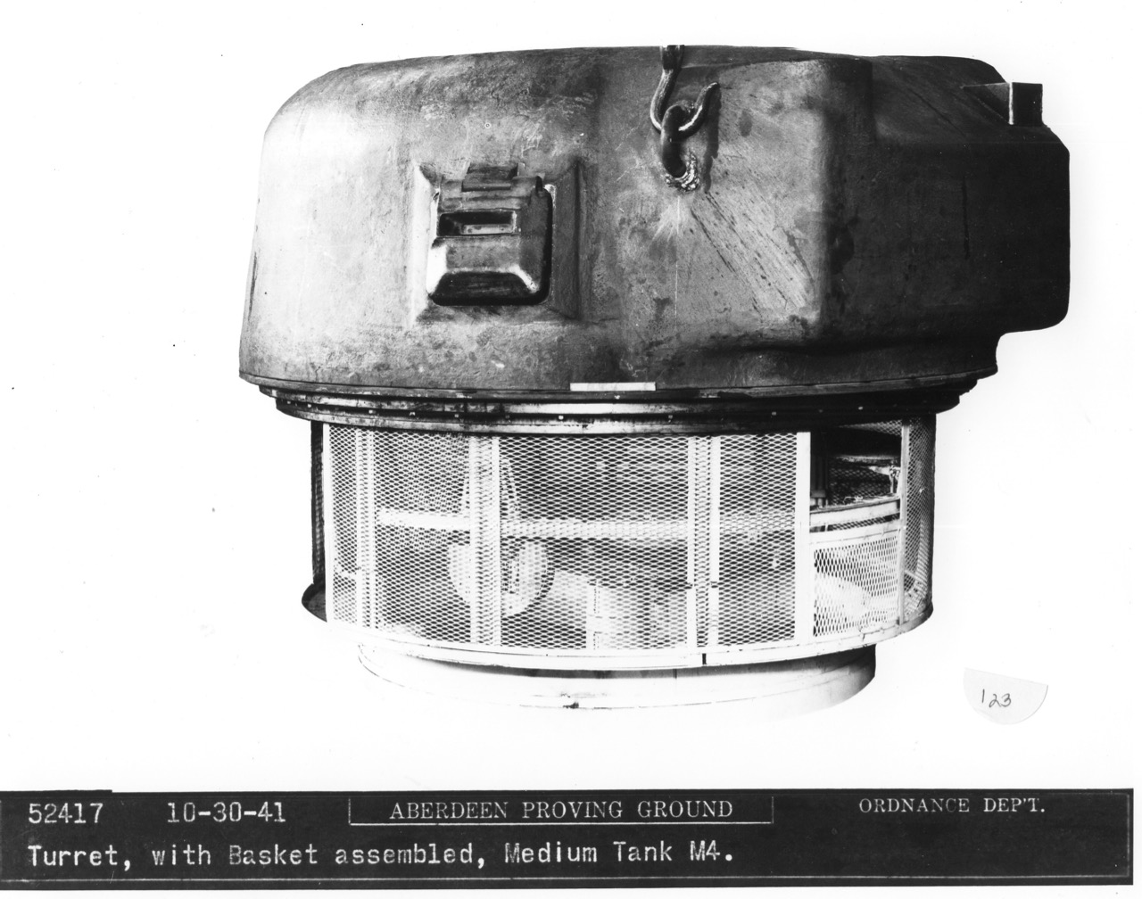
To be precise, I removed the lifting eyes, the ventilator on the turret roof and the small antenna base on the rear. Those can be seen in this somewhat well-known photograph:

Very early M4 turret.jpeg


… but that isn't a T6 turret (as is clearly stated underneath :) ). Despite having a pistol port with a protectoscope in it, this is a very early M4 turret, with lifting eyes and a second antenna base.

I filed all around the Asuka gun shield that's on the model until it fit. I first intended to enlarge the opening in the turret for it, but that would have shifted the shield to the right, so I felt it would be better to reduce the shield's size instead. It's still loose in the photo, because it needs quite a bit more work to be able to pass for the T6's shield.

Oh, and I scraped off the casting seam along the rear lower edge of the turret. Photos of the T6 show barely a seam here, but the resin turret had a pretty thick one.

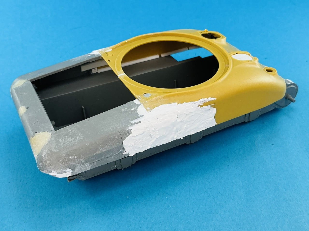
The tank's nose also had some work done to it:

IMG_3910.jpeg


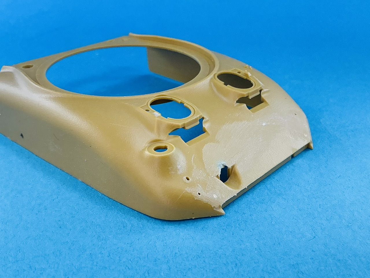
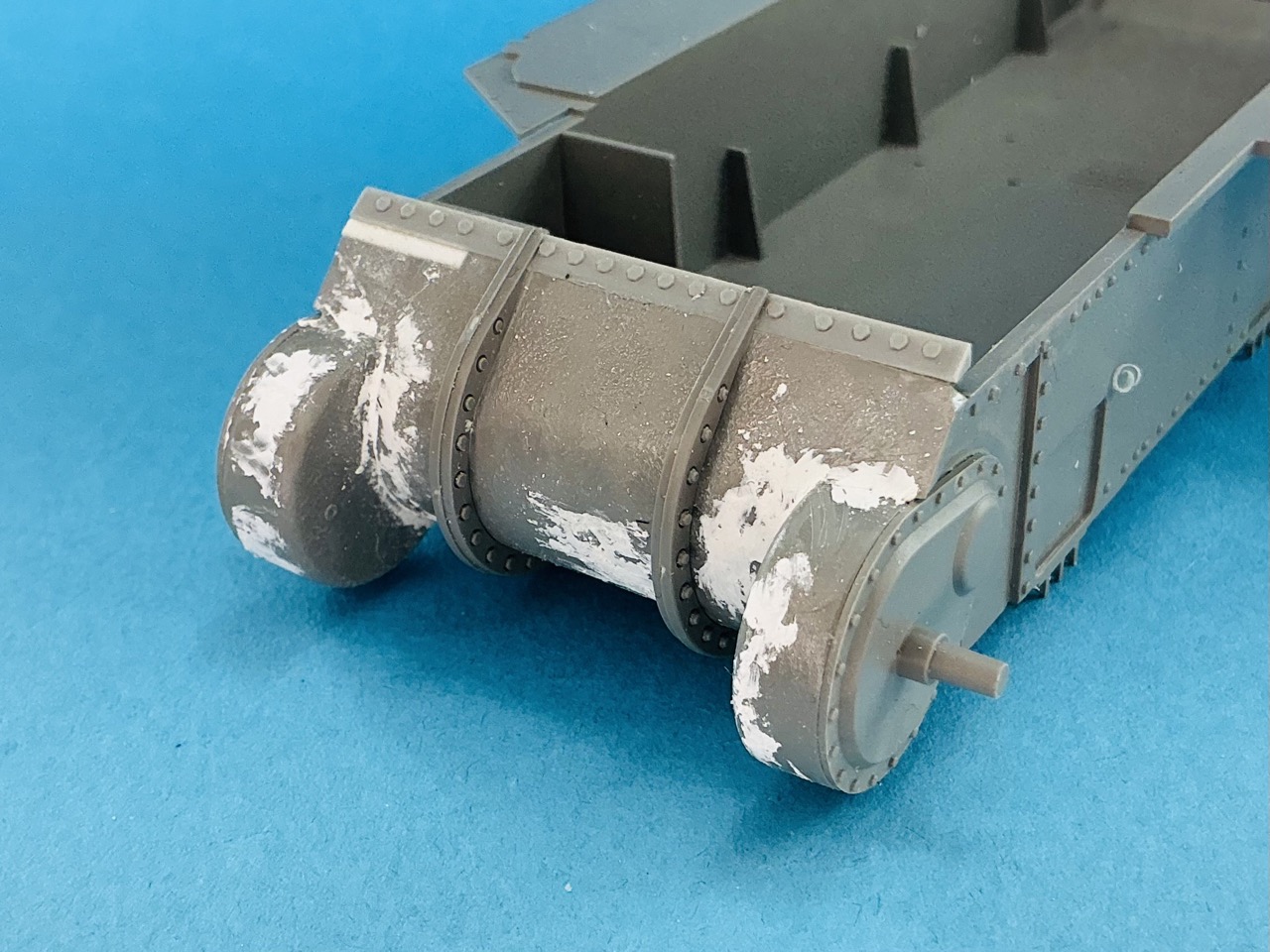
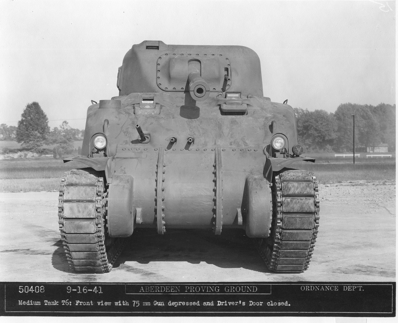
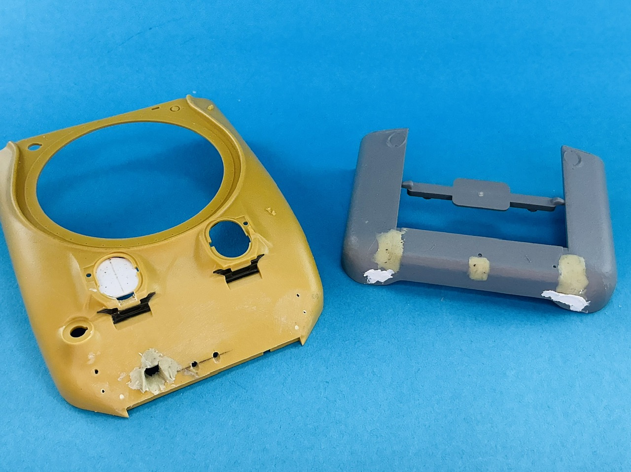
The white putty is partly for filling seams and partly to replicate the structure of this part of the real tank. Takom moulded almost everything here smooth, except the inner faces of the final drive "ears", so I used liquid cement and a stiff brush to add a little more structure. The strip with bolts is a lighter grey because it comes from my spares box, I suspect it's a Dragon part. I had to file its ends a little to fit the Asuka upper hull and fill two slots with plastic strip (not visible here because the vertical flanges with bolts cover them). The reason for using this part is because the M3's is shorter: the bit of white plastic at the top is there to fill the lower section here that was necessary on the M3 but not on the M4. On the real tank this was filled by welding in a piece, and that can be seen in photos:

T6 front view, gun depressed.jpeg


But I still have to replicate that :)
 
The running gear:

IMG_3911.jpeg


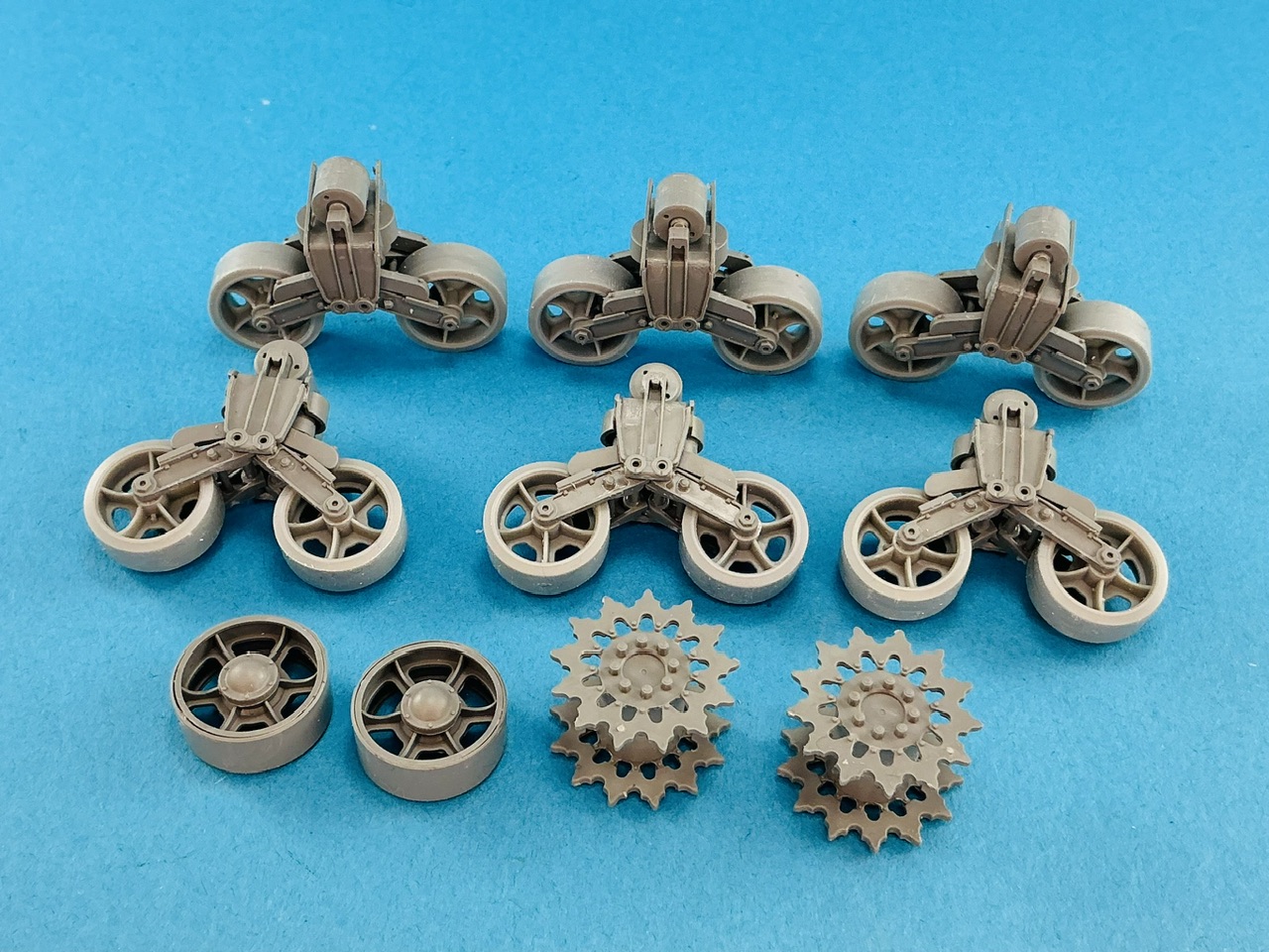
Because the photos of the T6 show it sat high on its suspension, I had to find a way to do that on the model as well. Takoms bogies, however, have been designed to sit at one particular height, and that height is too low for the T6. After some thought, the solution was to add an 0.5 mm spacer (part "C" for Asuka bogies, with the C sliced off because it adds extra thickness) in the top of the bogie, though that means the springs won't fit because the axle that's on them needs to sit in a slot in the bogie but that doesn't run down far enough. I cut about half a millimetre off both ends of that axle, then built the bogies with the spacer but without springs and levers (the shallow ^-shaped parts that sit on top of the wheel arms), and only then added the springs and levers, glueing the springs — but not the levers! — in place. I did have to shorten the C-spacer a little, because else it wouldn't fit inside the bogie. Anyway, after that I added the wheel arms, also without glue so that everything can be lined out later on.

Oh, BTW, the wheels aren't from MiniArt, as I said earlier, but Dragon. In any case, their shape is better than Takom's :)

I've also been busy with putty:

IMG_3912.jpeg


On the front I drilled two holes for the fixed bow machine guns, and used two-part epoxy putty to make the hole for the flexible one smaller. I added too much there on purpose so I can carve it to shape once it's hardened. At the back, the little overhang was clearly sharper in shape on the M3A1 than on the T6, and that also didn't have the central gutter that the Takom kit has. The white putty, from a tube, hides the taillights. All of this still needs sanding, of course :)
 
...so many corrections to get your build to where you want it to be!
I'm thinking that being very knowledgeable is a double edged sword... if it were me I'd never ever finish a model!
But you seem to know where to draw the line, and we get to enjoy your progress.😎
 
As an Amazon Associate we earn from qualifying purchases. Product prices and availability are accurate as of the date/time indicated and are subject to change.
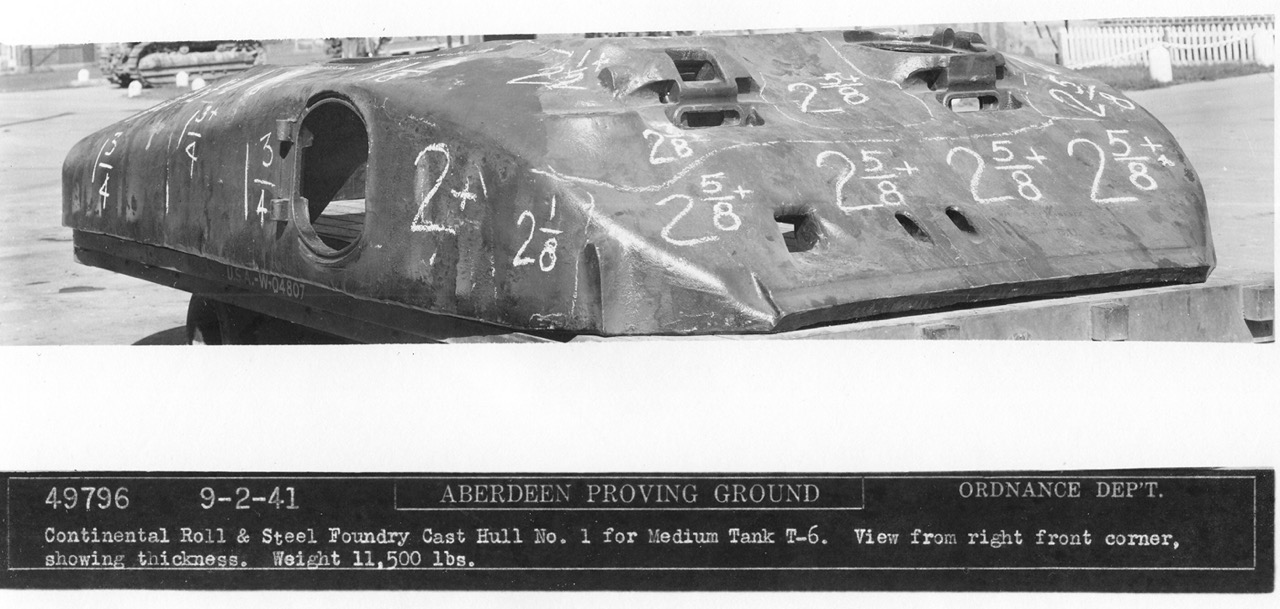
I simply draw the line at things I don't think I can build :) I've spent a good deal of time over the past few years looking at T6 photos, spotting the differences with an M4A1 and thinking about how to replicate those on a model — that certainly helps in building it relatively quickly. Even then, only when filing down the stuff on the glacis did I spot that it looks like there is a bulge there over nearly the whole width, but I'm not quite sure yet that it actually is there or if it's an optical illusion caused by somebody drawing chalk lines on another casting:

T6 hull casting No. 1.jpeg


(This is not the hull that actually went onto the T6: in another photo, taken from the left, there are casting marks visible that aren't there on the tank.)
 
At the back of the hull, both the M3A1 and T6 had a raised are in the lower edge, but the T6's was much wider. I sawed it out, using a handy ledge moulded on the inside as a convenient guide, and then moved the "corners":

IMG_3913.jpeg


I did have to bend those slightly to follow the curvature of the hull. Later, they will be puttied to blend in with the rest of the hull.

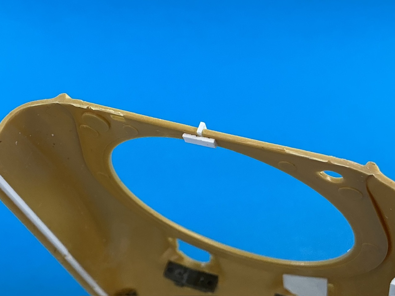
Much test-fitting and then measuring with callipers, showed that Takom's hull is slightly wider than Asuka's. That's a problem if you want to make sure they'll fit well together, but how to solve it? In the end I chose to saw through the turret ring and stick a piece of plastic strip in the gap, forcing the hull sides outward slightly so they'll fit better against the Takom hull rear. How much to add depends on the width of your saw blade, so I just tried a few thicknesses until I could feel barely any difference between the two parts when I fit them together as they should. After the glue dried, I of course cut and filed down the bit that sticks out.

IMG_3914.jpeg


Then I could fit the upper hull parts together:

IMG_3915.jpeg


To do this, i first glued a piece of strip (a leftover edge from a larger piece of plastic card) on both sides — for which I had to cut away part of the support moulded into each side of the Takom part — and set the upper hull correctly on the lower until the glue had dried. I then added two more strips for extra strength. Once it's well and truly dried, I can fill the seams.

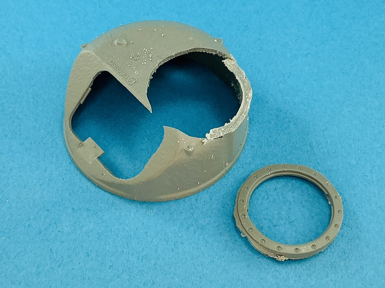
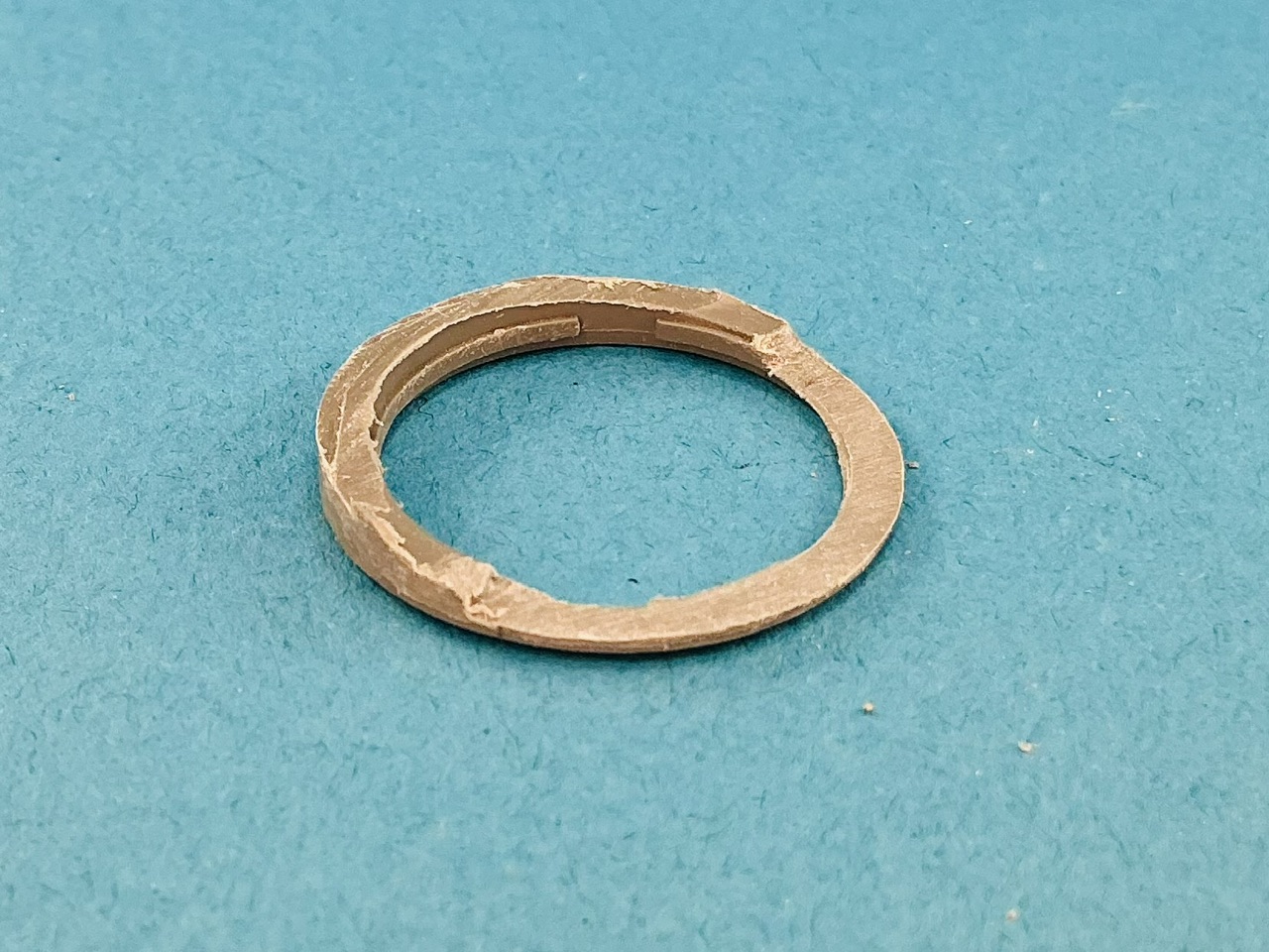
In the meantime, I turned to the turret. To allow the machine-gun turret to fit on it, it needs a turret ring, which of course isn't a separate part in the Takom M3A1 kit. No half measures, then:

IMG_3916.jpeg


After much filing, first to make it properly round and then to greatly thin it over about half its circumference:

IMG_3917.jpeg


I can highly recommend a job like this for anyone wanting stronger fingers and biceps :) Anyway, after much test-fitting and more fettling:

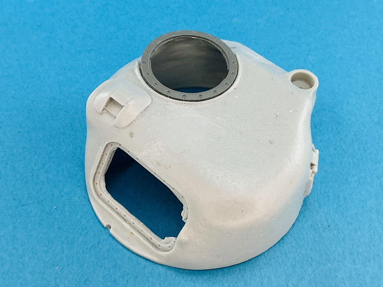
IMG_3918.jpeg


The hole in the turret also had to be enlarged, so that the thicker part of the ring fits inside the hole instead of lying on top of the turret. I could have filed the whole ring down, of course, but this way is a lot less work :)
 
On with this one now the Comet is largely done. I had puttied and sanded the seam between the two hull parts, but forgot to take a photo of it. However, I could still feel it, so I added more putty:

IMG_4056.jpeg


I think I now have a reasonable impression of what it's like to repair damaged cars ;) I put a ruler against the hull sides and made pencil marks where it touched the plastic — you can just make them out next to and under the putty. Hopefully, this layer is thick enough that I can sand it flat and no longer feel the slight hollow near the seam. On the left side, it needed less putty but still some.
 
Eh … I _think_ I might just stick to a block of wood with some sandpaper on it for now ;)

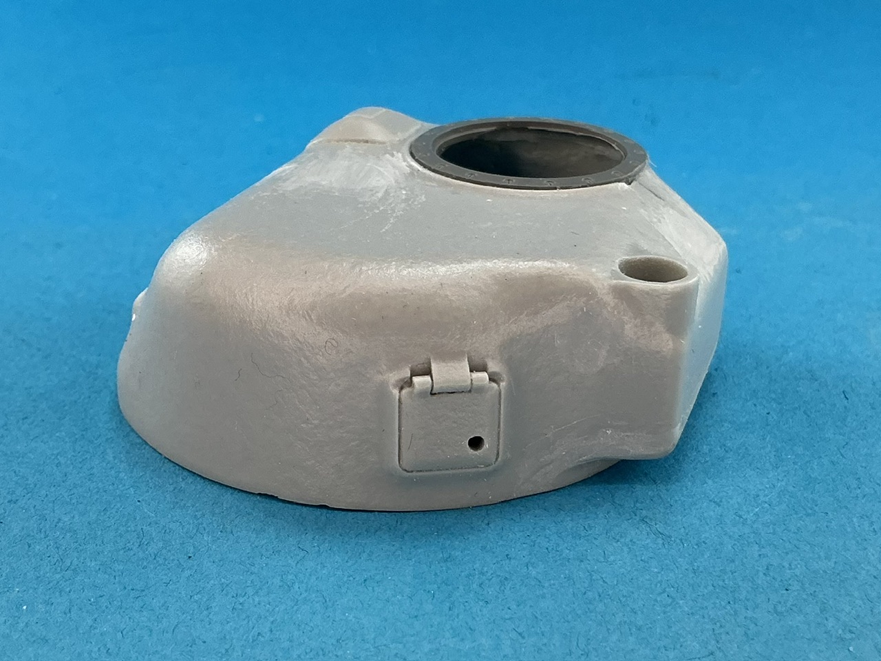
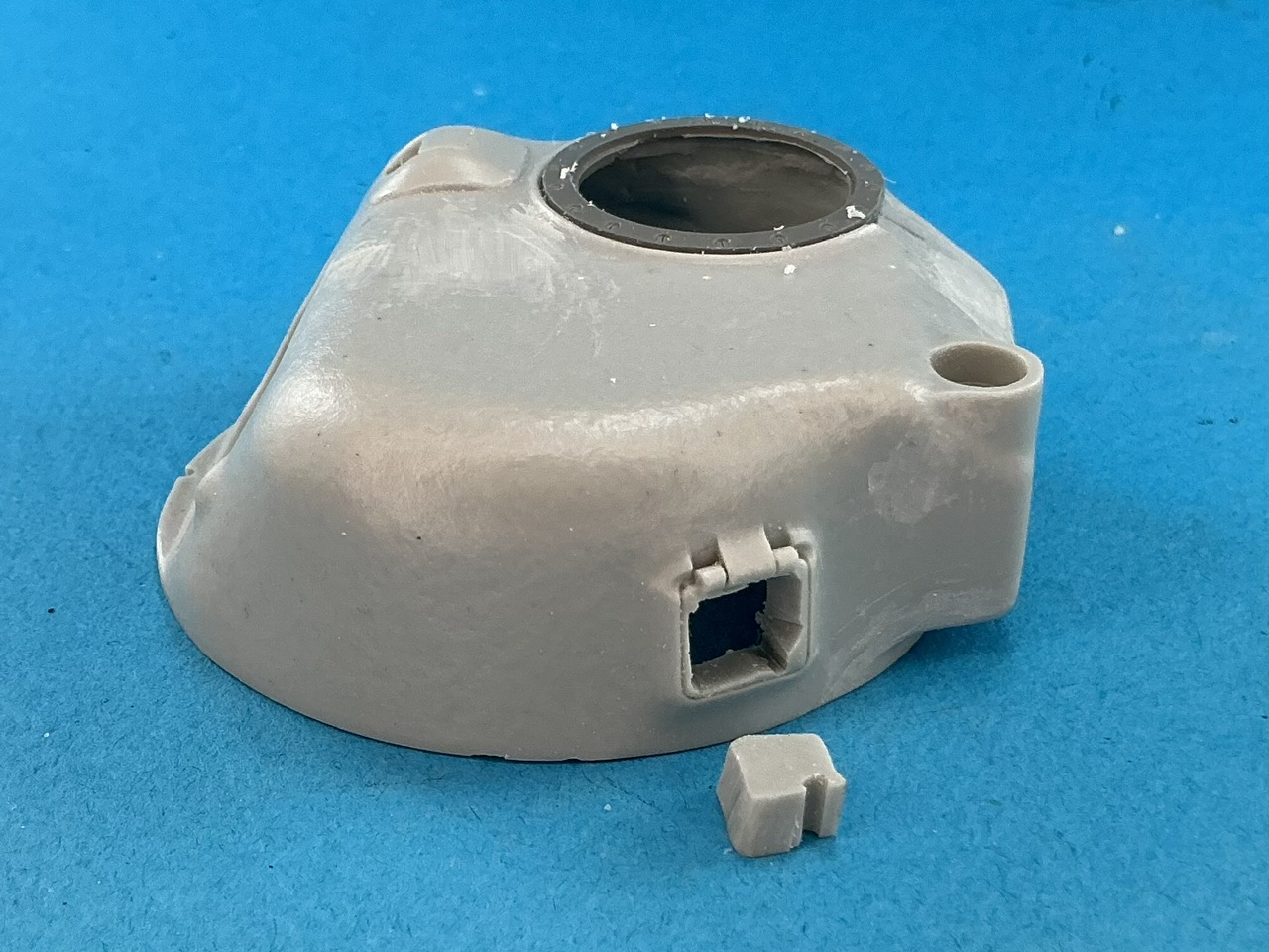
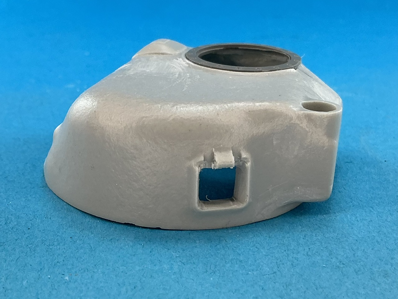
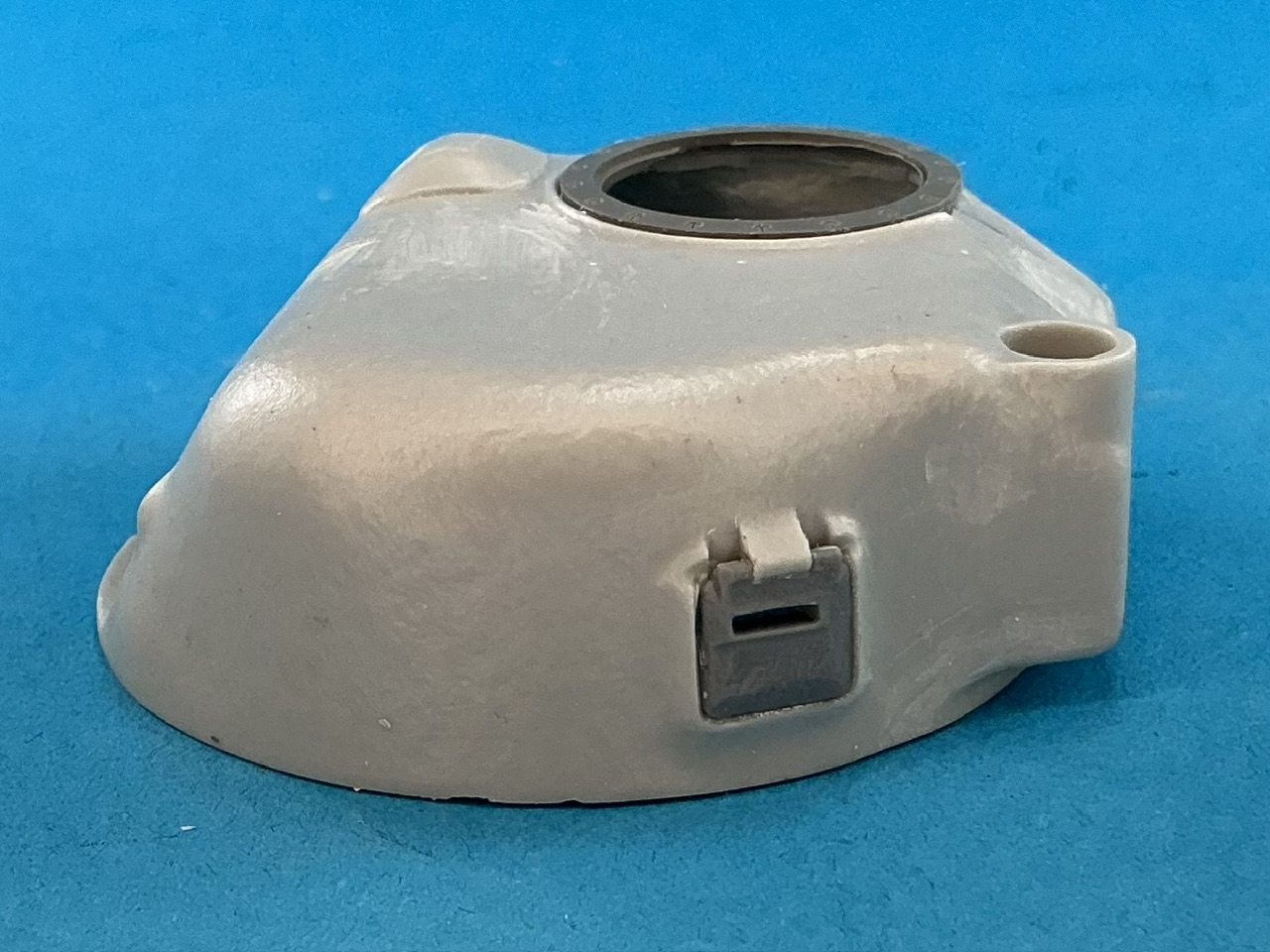
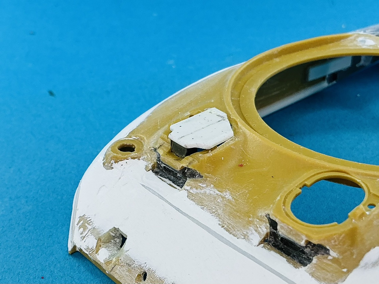
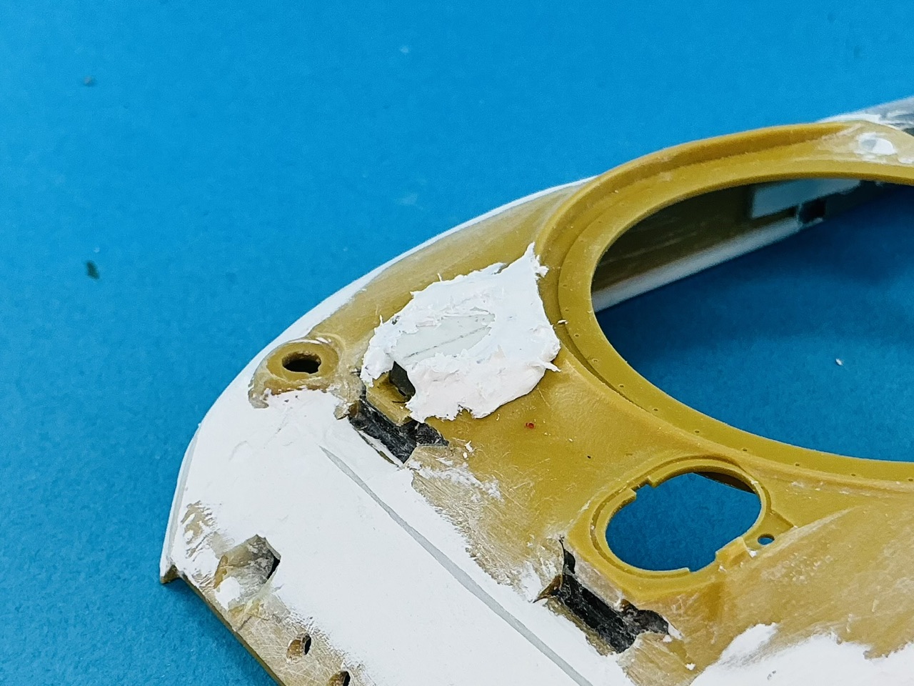
The T6 turret had a vision block in the flap for the pistol port on the left side of the turret, like in the M3's ports, but on the Sherman this was replaced by a plain flap. On the Panzer Art turret, the flap is cast into the turret, so I thought the easiest solution would be to just remove it:

IMG_4057.jpeg
IMG_4058.jpeg
IMG_4059.jpeg
IMG_4060.jpeg


I drilled a hole through it (first photo), stuck a jeweller's saw through that and sawed it out (second photo) and then cut the remaining bits away with a knife (third photo). That was fairly easy, as resin is soft and easy to carve with a sharp knife. You shouldn't try to take everything off in one go, though: it's better to cut away thin layers until you reach where you want to go. It also doesn't need to be carved away to the full depth of the turret shell — all that matters is the flap. One from a MiniArt M3 fit neatly first time (fourth photo).

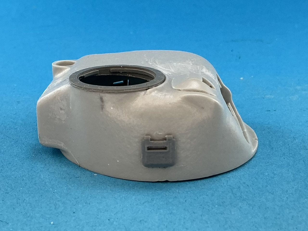
A notable difference with the M4's turret is that there wasn't just a pistol port on the left rear (at about 8 o'clock) but also on the right at 3 o'clock:

IMG_4061.jpeg


For this, I used a second MiniArt flap, whose rear face I cut and filed flat, and I also filed a slight flat in the side of the turret where the flap goes. I glued it 4 mm above the turret's bottom edge, the same height as the flap on the left. Now I need to find a good way to add the lip around it.
 
IMG_4062.jpeg


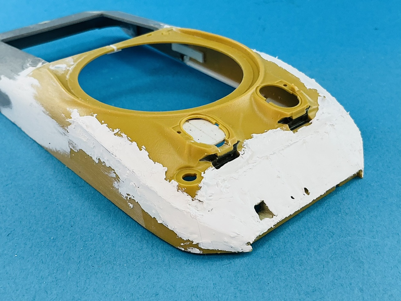
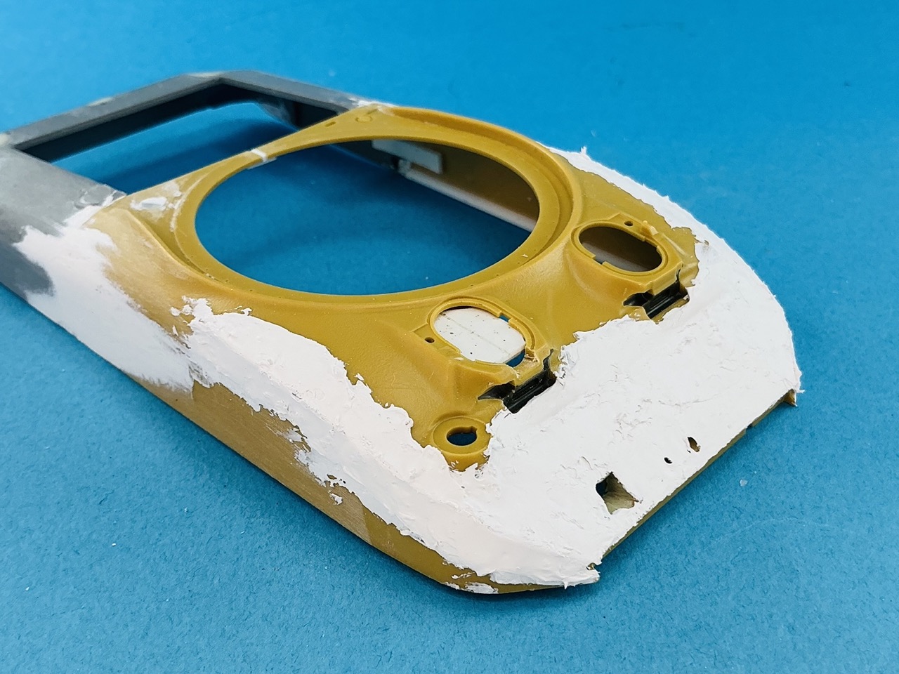
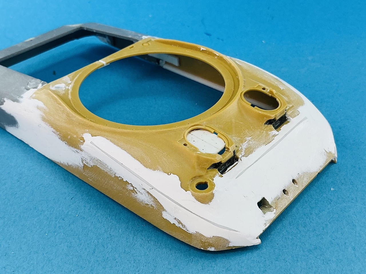
I sanded the sides with a length of wood, maybe 15 by 4 cm, to which I glued waterproof sandpaper. It's long enough to prevent me from sanding a hollow into the putty, as the idea is that once it's against the plastic in front of and behind the putty, I'm at the correct depth. This work isn't quite done yet, but because I also need to correct the front hull shape with putty, I'll do that first and then continue sanding. For that reason, there is now some 0.88 mm plastic rod glued to the hull, which will serve as the "aiming mark" for the putty.
 
The snow got even worse:

IMG_4064.jpeg


That is to say: because of shrinkage around the plastic rod I applied more putty yesterday, and today I sanded and occasionally scraped it to get it into shape better:

IMG_4065.jpeg


There are still some lower areas that needed a bit more putty afterward, the corners of the hull are now too sharp (instead of too rounded) and it needs a bit more filling and sanding still, but it's getting there. On another forum, someone commented that this is more plastering than puttying, and I don't think he's far off the mark :)
 
The snow got even worse:

View attachment 183787

That is to say: because of shrinkage around the plastic rod I applied more putty yesterday, and today I sanded and occasionally scraped it to get it into shape better:

View attachment 183788

There are still some lower areas that needed a bit more putty afterward, the corners of the hull are now too sharp (instead of too rounded) and it needs a bit more filling and sanding still, but it's getting there. On another forum, someone commented that this is more plastering than puttying, and I don't think he's far off the mark :)
I messed up on a ZM kit and had to do some plastering" too. So much that I used styrene strips to build an area up before putting down putty!
 
I used styrene strips to build an area up before putting down putty!
After doing the above, I discovered that the actual shape of the T6 was such that it would have been better for me to do something like that too in areas :) This will become clear later, as I applied more putty yesterday in a thick layer that needs to thoroughly dry first before I can continue.
 
How much putty did you add to this model! And btw, which putty do you use?
 
This is all Tamiya white putty, which sticks well and is very easy to sand. It looks like a lot more than it is, really :) The plastic rod is 0.88 mm diameter, so the layer on the hull front tapers from that down to zero at the lower edge. The thing is that the real T6 had a flat glacis plate, which was revised to a curve on the M4A1, so I need to make it flat again. (The way they changed it to a curve was to start at the bottom edge of the glacis and then draw a circle section from there to where the step is near the top on my model, just in front of the vision blocks. This means that the original flat glacis was outside the later curve, so I can build it up with putty.)

I did consider using plastic card to make the glacis, but felt it would be difficult to get it to blend well into the lower edge, so putty it had to be.
 
This is all Tamiya white putty, which sticks well and is very easy to sand. It looks like a lot more than it is, really :) The plastic rod is 0.88 mm diameter, so the layer on the hull front tapers from that down to zero at the lower edge. The thing is that the real T6 had a flat glacis plate, which was revised to a curve on the M4A1, so I need to make it flat again. (The way they changed it to a curve was to start at the bottom edge of the glacis and then draw a circle section from there to where the step is near the top on my model, just in front of the vision blocks. This means that the original flat glacis was outside the later curve, so I can build it up with putty.)

I did consider using plastic card to make the glacis, but felt it would be difficult to get it to blend well into the lower edge, so putty it had to be.
Do you thin the putty at all? I've found it's easier to work with, doesn't set as quickly and easier to maneuver when I thin it.
 
Not for this, it's all straight from the tube here. If you need to build up thickness, that works better than thinning it for longer working time — it's not necessary to have it workable for long here, it just needs to be soft enough to be troweled into place with a blade-type sculpting tool :)

For things like replicating cast parts, I do thin it, with the same hardware-store solvent I use to glue plastic parts with.
 
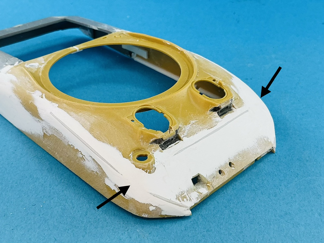
More putty, sanding, filing and scraping, though it's hard to see because everything is white :)

IMG_4066.jpeg


I added more at the arrows, so that the flat glacis extends all the way to the sides. I also rounded off the upper edges of the sides a little, because they were a little too sharp.

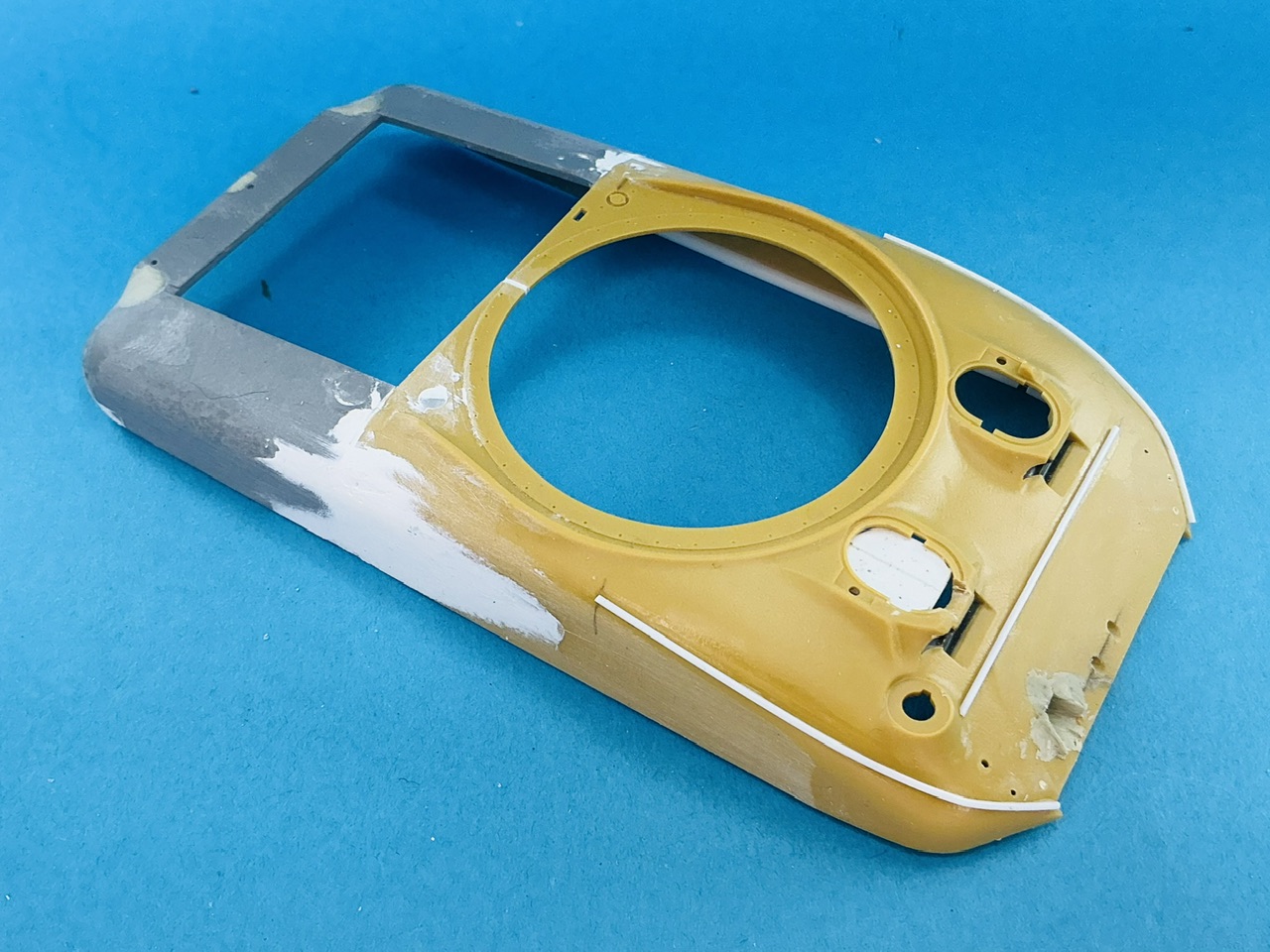
You can also see that I took out the piece of plastic card I had glued under the bow gunner's hatch opening. That was meant to support two-part epoxy putty from which I intended to make the hull roof, but after looking at photos some more I reached the conclusion that, for me anyway, it would be easier to build from plastic card and putty from a tube. I first built the bow gunner's sight from some sprue and then adapted the same piece of plastic card to sit on top of it:

IMG_4069.jpeg


Notice here that the roof above the bow gunner's position is horizontal instead of sloping down slightly like the hatch does. It took a moment before that really clicked, and until then I thought there wouldn't be room for the sight, but it turns out the roof at the front is clearly higher above the hull than at the rear. The entire top of the roof is level with the top edge of the splash guard around the turret ring.

Out with the putty again!

IMG_4070.jpeg
 

Latest posts

Back
Top