Beginner Airbrusher Needs Help

Scale Model Addict - Model Tips, Guides, Tools & Tech, Tutorials, and Community

Help Support Scale Model Addict:

Your AB , supply hose and compressor use 1/8" BSP threaded fittings ( British Standard Pipe )

On the compressor side of that filter assembly you'll need…

You'll need 2 hose clamps that will accommodate 3/16 tubing ( 1/4" ) , which you might already have on hand ? , and can definitely get local , or add them to the Amazon order .
Okay, good deal. Prepping the Amazon order. Is all this fairly intuitive to assemble?

Or would it just be easier/cheaper to get a whole new compressor?
 
happy to help .
that's the most cost effective route with your current setup .
If you were to get a tanked compressor you'd still want a moisture trap in the line anyways .
 
I am following this post, sounds like I may have the sputtering problem also. So am I understanding this right, it may be a big help to have a portable tank and install the water filter on that would eliminate water vs having the filter on outlet of the compressor head?
 
As an Amazon Associate we earn from qualifying purchases. Product prices and availability are accurate as of the date/time indicated and are subject to change.
Any and all additional volume available for the air to cool down and the moisture to drop out is a plus , whether that's additional hose or a tank .
Just make sure the collected moisture can be removed via an inline water separator and/or tank drain .

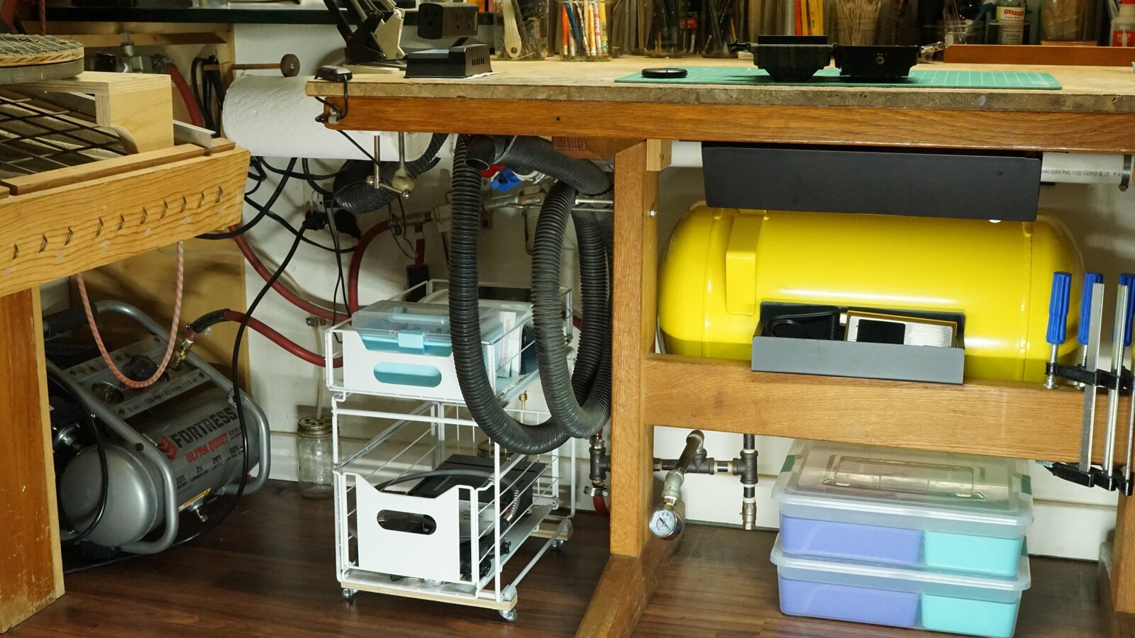
I spray from an 11 gallon tank that I charge up with a 2 gallon compressor .
The tank charged up to 130 psi will generally last for many days and recharging it takes only a few minutes .
I have a bunch of filters between the compressor and 11 gallon tank and between the tank and airbrush .
All the water is removed before it gets to the tank though , so the additional filters between the 11 gal tank and the AB , both inertial and desiccant type ,are kinda overkill .
I love overkill .

DSC06217.JPG
 
My thoughts exactly. I thought the filter attached at the head outlet was kind of useless as far as non-water intrusion, and the small separator/filter was overwhelmed from the get-go. Thanks
 
The relative humidity in the room is normally 45-55% so probably 99% of the water gets trapped in the compressor tank .
That's a great little compressor -- super quiet . Of course , I only run it briefly to charge everything up so I never have to hear a compressor running when airbrushing .
I take the compressor out the front door occasionally and open the drain ,, unless it's completely discharged , then I just do it right there at the bench .
 
happy to help .
that's the most cost effective route with your current setup .
If you were to get a tanked compressor you'd still want a moisture trap in the line anyways .
So all the parts got delivered. No instructions with the filter (wasn't surprised). I feel like there's too many parts. I'm assuming the general setup is airbrush hose from compressor to filter, clear plastic hose to connect the two sections of the filter (with the hose clamps?), and then airbrush hose from filter assembly to airbrush. With the various adapters to connect the hoses and tape around the brass connectors? Am I missing anything?

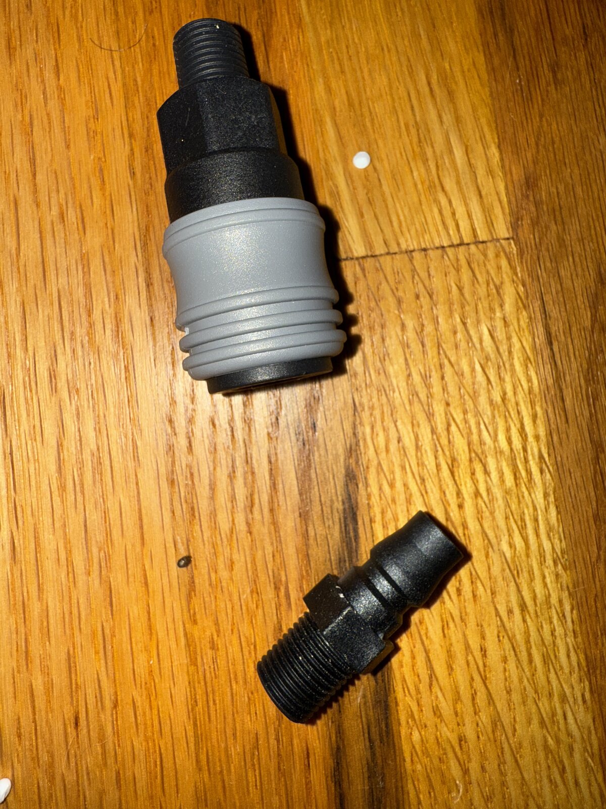
I'm not sure what these parts are that were packed with the filter.

IMG_8203.jpeg
 
Just ignore those 2 .
those are male / female quick connects .

I lined out the exact order of the installation of fittings and the 3/16 tubing above . in that Amazon order .

the clear tubing connects the compressor to the filter .
The filter / regulator should have direction of airflow marks on it , an arrow . Should be on all 3 elements . maybe not , but at least one of them ,, or an " in " and " out " .

your existing AB hose connects to the outlet of the filter via the fittings spec'd out above .

In that component list above where I said , " Then on the compressor end of that hose .. " , the hose there is the clear tubing .
 
Last edited:
So I have it all connected but it's not working. All the air is escaping out of the release valves at the bottom of the filter chambers. I don't have much experience with this kind of thing but I'm pretty sure I've got all the connections right and I checked to ensure everything is tight. If I'm understanding this right those valves should close when the air starts running but they're not.
 
pull them down to shut them .
They require a minimum pressure -- pump up the compressor output pressure / regulator output
 
pull them down to shut them .
They require a minimum pressure -- pump up the compressor output pressure / regulator output
They're spring loaded and doesn't look like they can be manually closed. I tried the compressor at max psi but no difference. Is the filter just designed to work with a higher capacity air flow?
 
turn the pressure regulator knob counterclockwise all the way ( to minimum pressure output )
with the compressor running pull and hold both drains shut until pressure builds up in the bowls
 
turn the pressure regulator knob counterclockwise all the way ( to minimum pressure output )
with the compressor running pull and hold both drains shut until pressure builds up in the bowls
So that worked to close the valves. But there's no air making to the brush, and the compressor still runs like it's pushing air.
 
there will be no air to the AB with the regulator knob all the way open .
turn the knob clockwise to increase the output .

and hold on , let me pull up your compressor
 
you have it oriented correctly ?
The Amazon page shows the regulator at the output side , the side toward the AB

Check for leaks ,
That compressor has low volume capacity so a small leak or leaks will keep it running .
Use soapy water around the connections
 
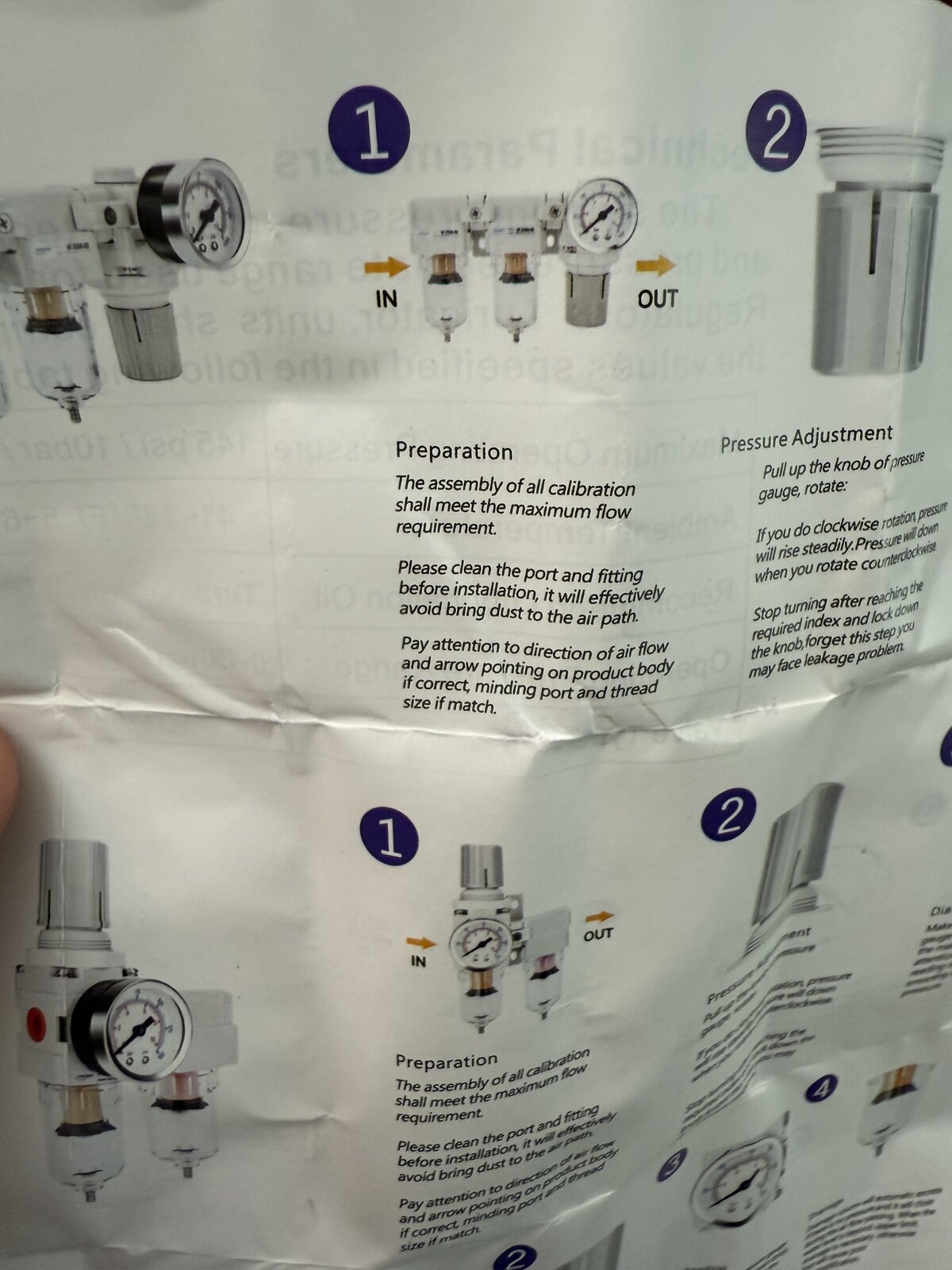
I see what you're saying about the picture on Amazon. It shows the compressor in on the right. But that's weird because the diagram said air in on the left and out on the right.
 
are there direction of flow markings on any of the components ,, or and " in " , " out " ?
 
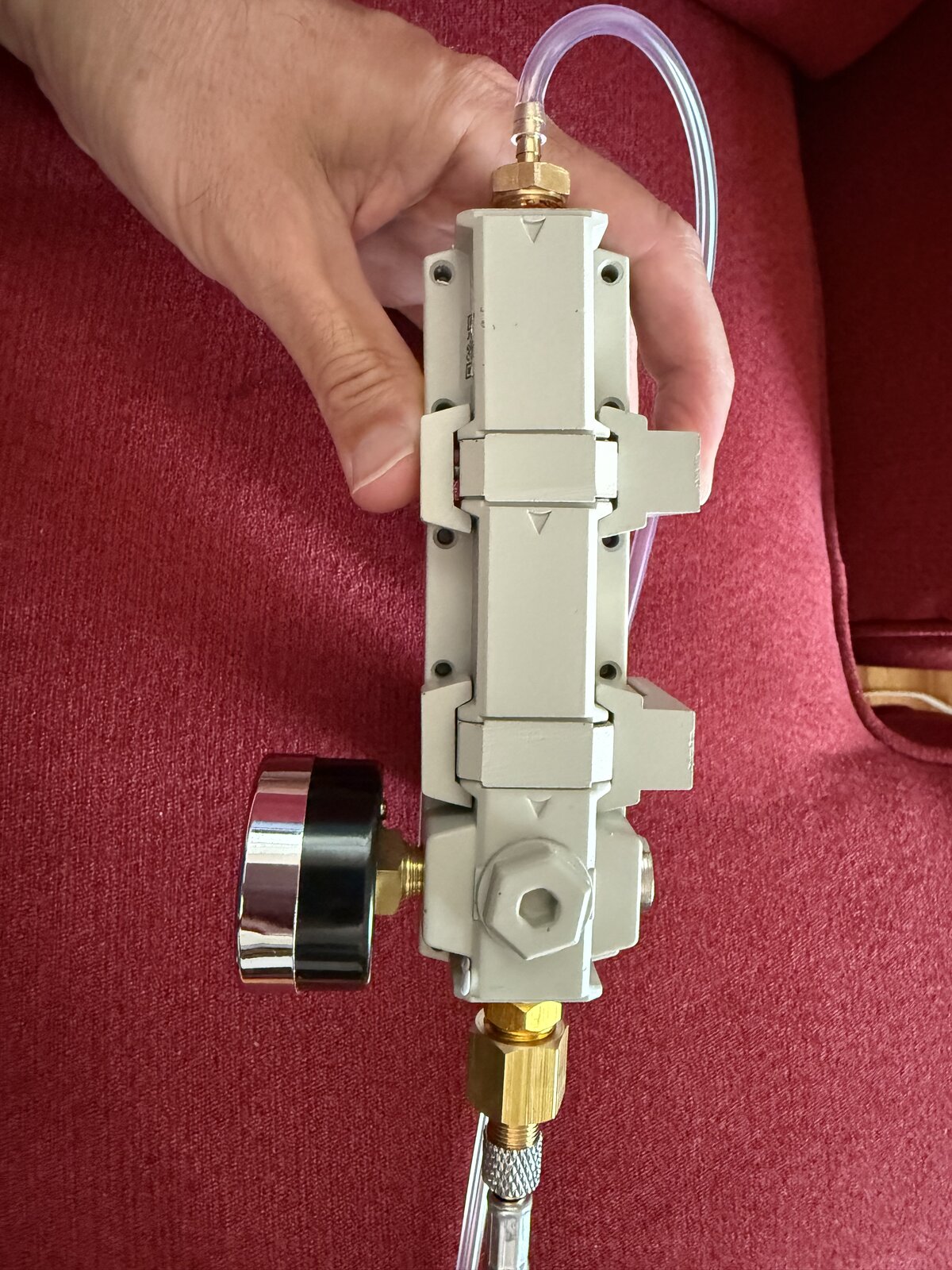
The arrows on the top are indicating airflow direction right?

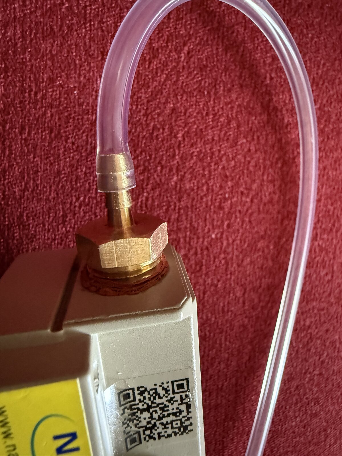
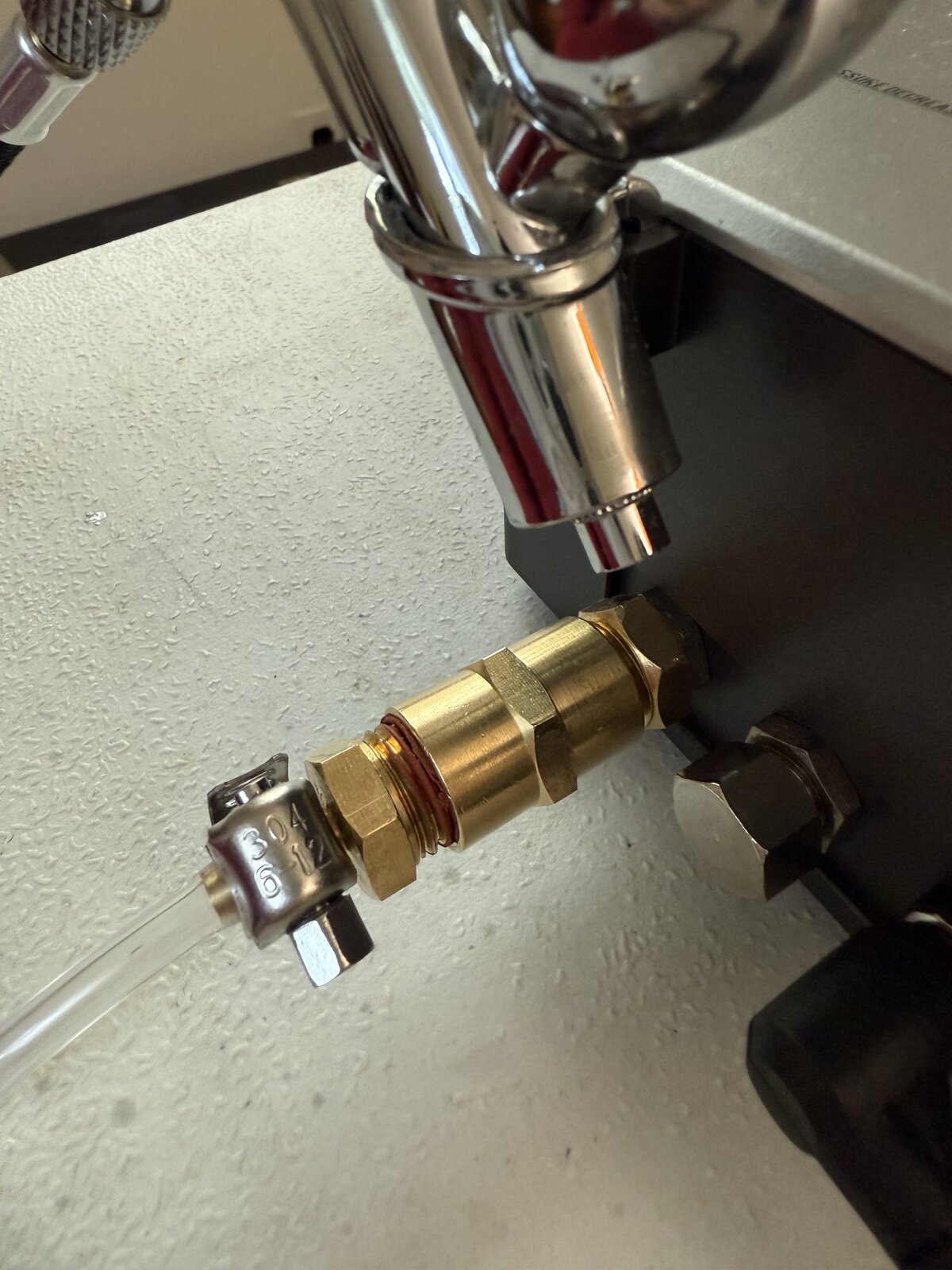
I think air is escaping from one of the two ends of the clear hose. Or both. The brass connectors had sealant coating on them, and as you can see, it bunched up and made it difficult to fully tighten them. I tightened them until they wouldn't turn anymore. I did have a hose clamp on the filter side of the clear tube but removed it to trim the tube because I thought it might have had a hole in it. I wasn't able to push the clear tube on all the way at either end. Got them two thirds of the way and then clamped them.

IMG_8208.jpeg


IMG_8210.jpeg


IMG_8211.jpeg
 
the flow is correct

WHERE ARE THE HOSE CLAMPS ???
you need hose clamps to secure each end of the clear tubing
 
I did have a clamp on it. I took it off again to trim the end of the hose.

Is it essential to have the tube onto the fitting all the way? Because it was tight AF and I could only get it on 2/3s-3/4s of the way.
 
just and FYI , the filters and regulator can be assembled in any order desired as long as the air flow direction is consistently correct .
The image showing the supply air entering the regulator is therefore possible and why it shouldn't be relied upon -- always ensure the flow arrows on the components are aligned correctly .

You're good with how you have it .

with the compressor running you won't be able to hear any leak so use soapy water on every joint
 

Latest posts

Back
Top