M4 (105 mm) HVSS on Okinawa

Scale Model Addict - Model Tips, Guides, Tools & Tech, Tutorials, and Community

Help Support Scale Model Addict:

Now I need to make myself break out the Sylmasta A+B and make the mantlet cover and a bunch of sandbags … I don't enjoy working with two-part epoxy putties much, can you tell? :)
 
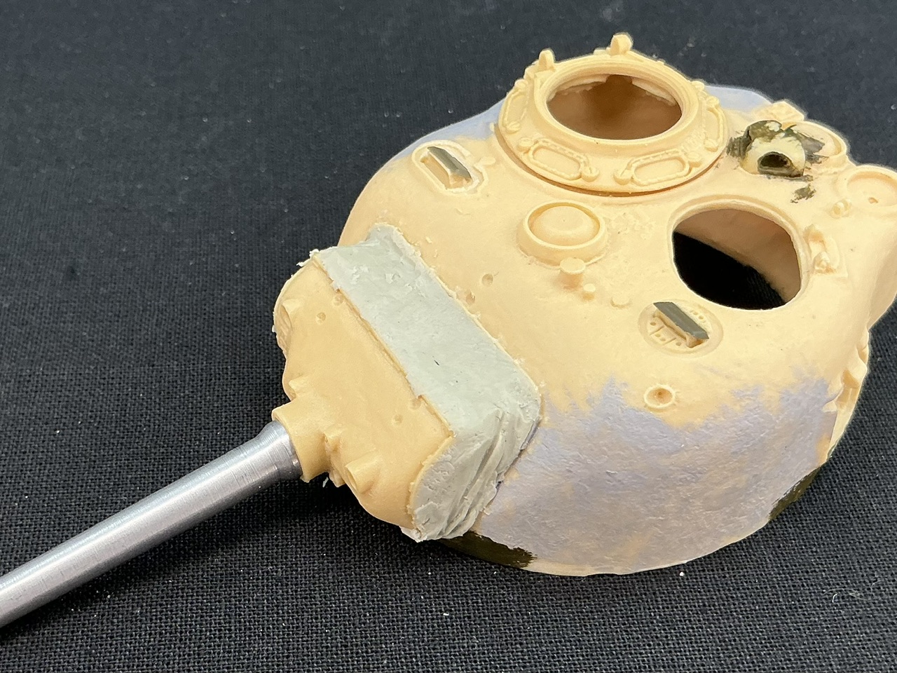
With Magic Sculp, I made the canvas cover for the gun shield:

IMG_1906.jpeg


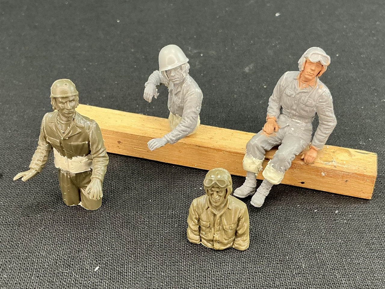
Earlier, I had scrounged up a crew, and because I had the Magic Sculp mixed up and left anyway, I also made a few small changes to them:

IMG_1907.jpeg


From left to right first the assistant driver, an Asuka figure whose pistol belt I cut away and whose coveralls I modified into a jacket and trousers. Then the commander, which is an upper body from MiniArt with a helmet from the spares box, and a little bit of lower body made from the remains of the Magic Sculp because when he's in the hatch it was just a little too noticeable that his body ended at his waist. The driver is from Tamiya with Asuka goggles, and the loader is another MiniArt figure with lengthened trouser legs so his uniform can pass for 1945 Pacific style, so without leggings — it doesn't need to be any better than this because his legs will be dangling in the loader's hatch. His flesh has a base coat of paint from a previous employment opportunity that did not come to pass.
 
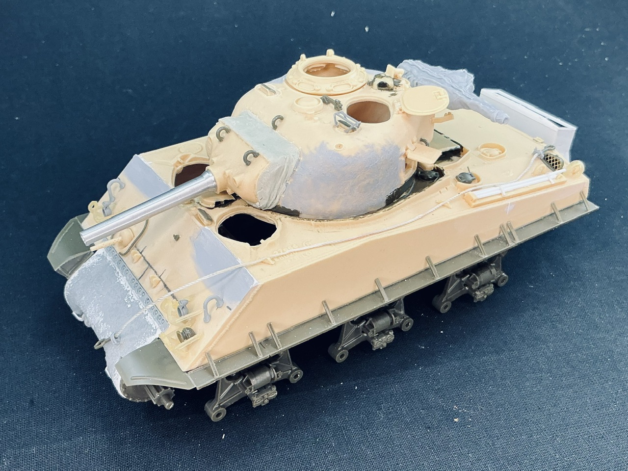
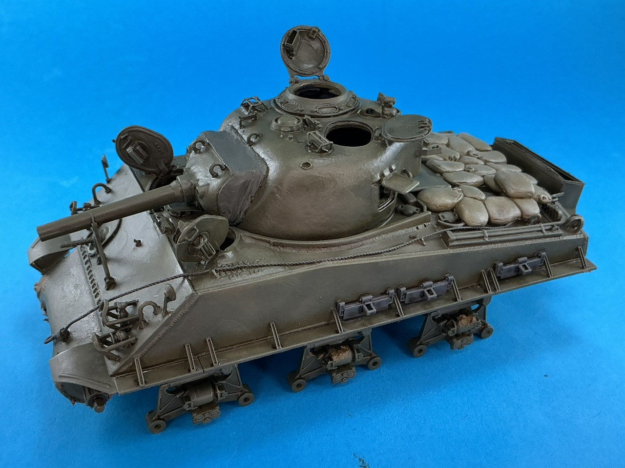
Here's an overall shot of what I have now:

IMG_1910.jpeg


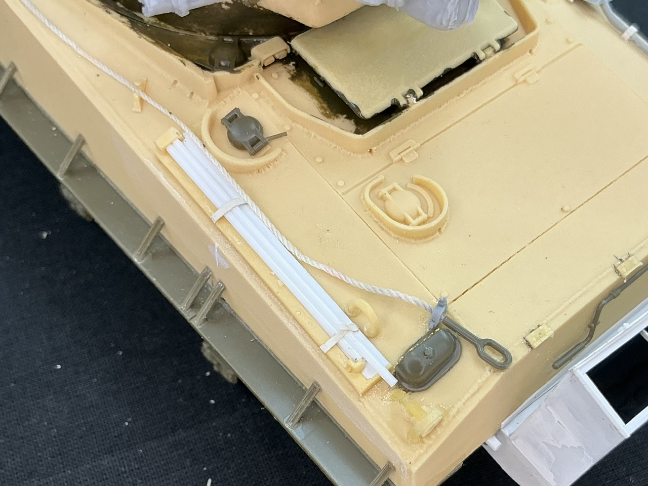
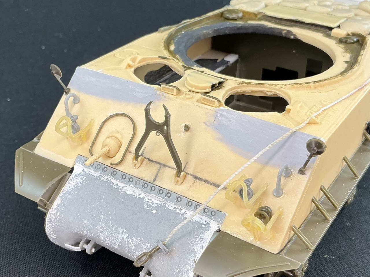
I did remove the tow cable and replaced it by a thinner one, for which I also had to use different eyes:

IMG_1911.jpeg


Because the old cable was threaded through the front and rear clamps and was partly glued to them, I had to cut those off the model. Fortunately, I have a bunch of those from Tiger Models in grey resin, so that was not a big deal.

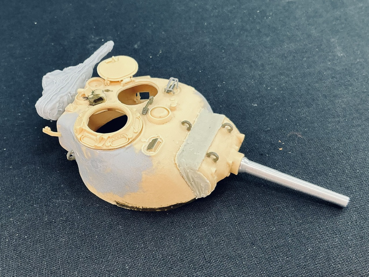
And now the canvas cover is done, I could continue adding details to the turret:

IMG_1915.jpeg


The lifting eyes, periscope covers and folded-down support for the machine gun barrel are from Asuka, the periscope brush guard dfrom RFM (I think), and the covered machine gun (which is not glued on yet) on the back is also by Tiger Models. To make sure it won't break off, I drilled out the support for it, inserted a bit of 1 mm brass rod, and glued that into a corresponding hole I drilled into the back of the turret. To the loader's hatch, I added a grab handle (not visible), and I need to add some more details to the turret before it's done.
 
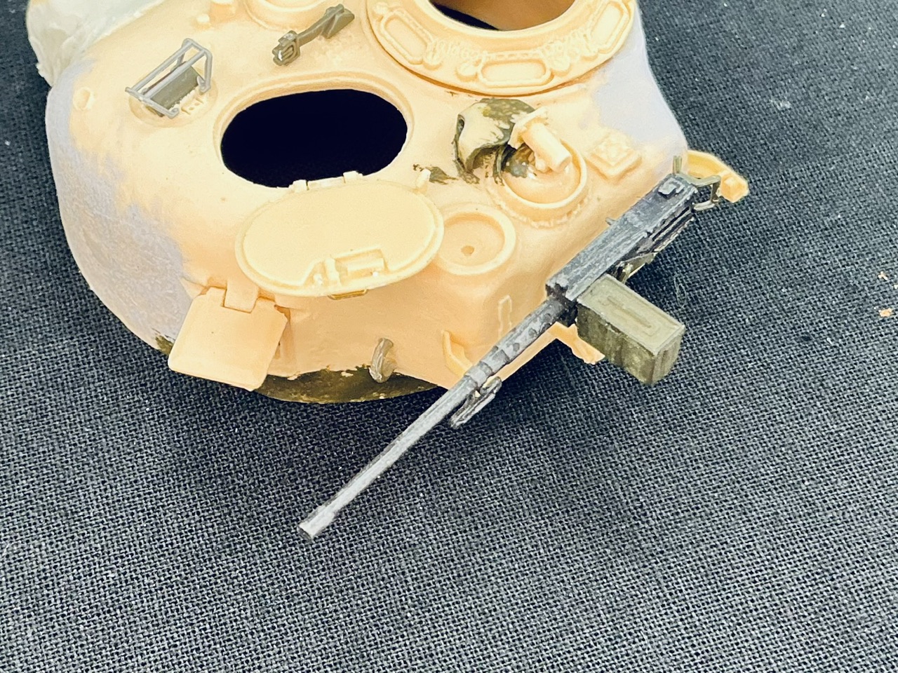
After more peering at the available photos, I replaced the .50 calibre on the back of the turret by a better one:

IMG_1916.jpeg


A very old, already painted one from Italeri :) Partly because it's impossible to put the Tiger Models gun in the transport clamp (which isn't on my model yet), but also because that Tiger Models gun is in a special cover with zip etc. while on the well-known photos from Okinawa, there appears to be a simple tarp over the weapon, with that transport clamp over the tarp. (This gun is still loose too, by the way. It's "better" because it will get covered up completely, and for that I prefer to use a part that's as poorly detailed as possible yet still of the right shape and size.)
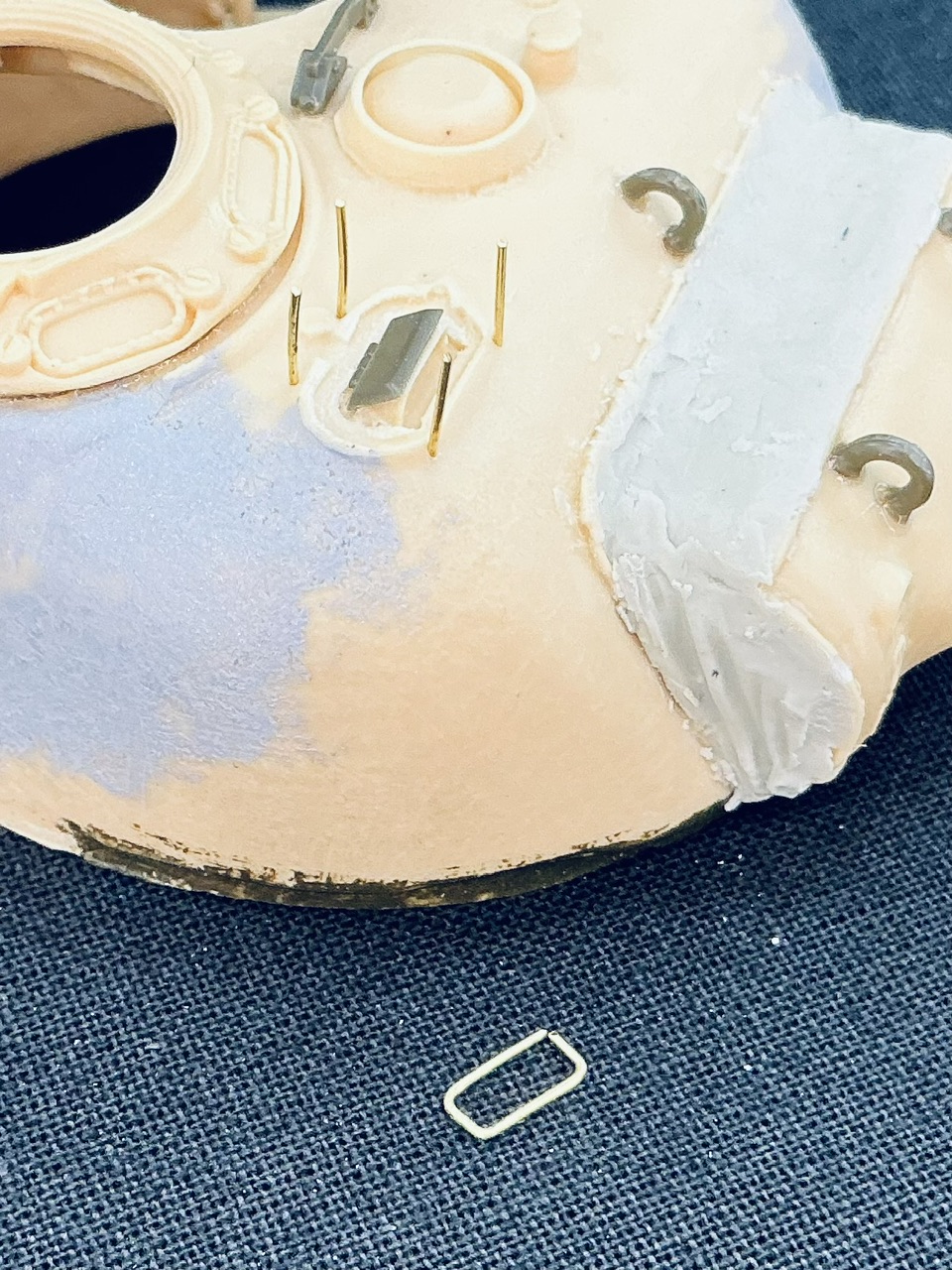
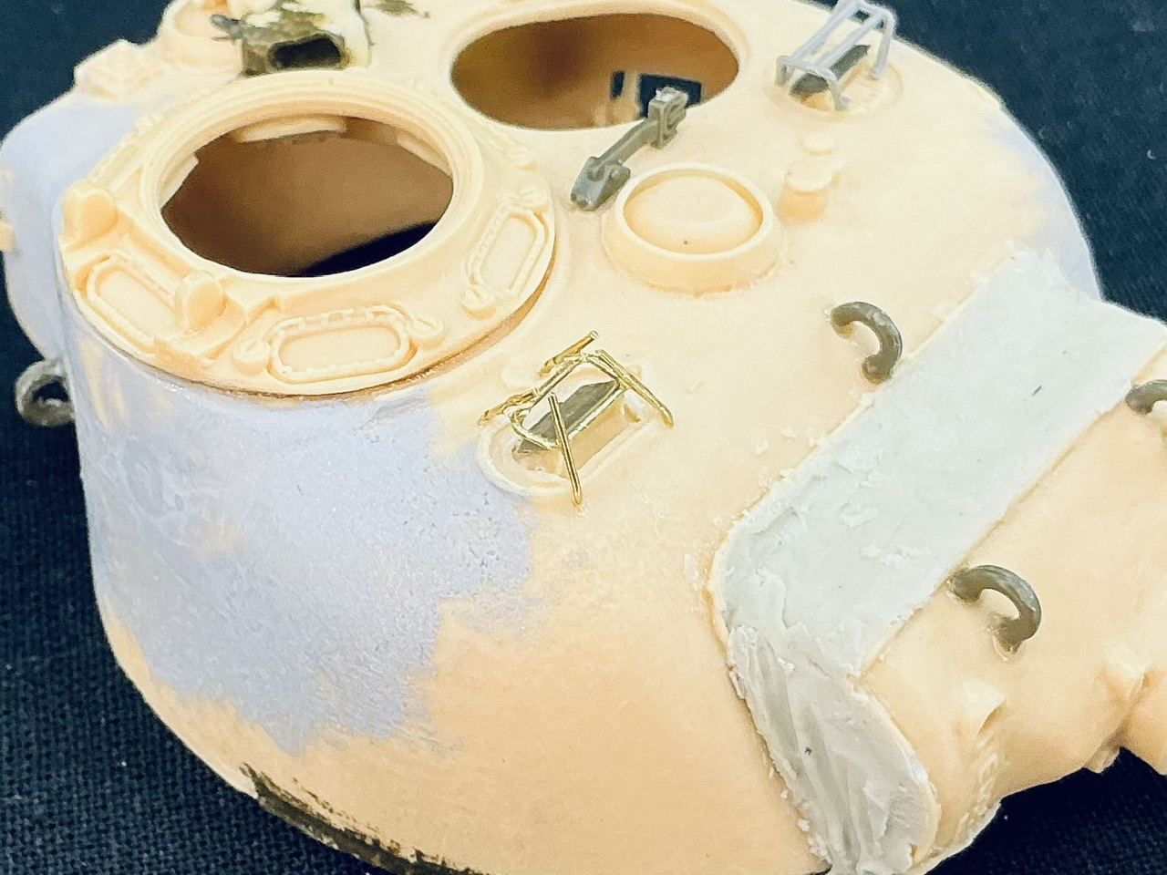
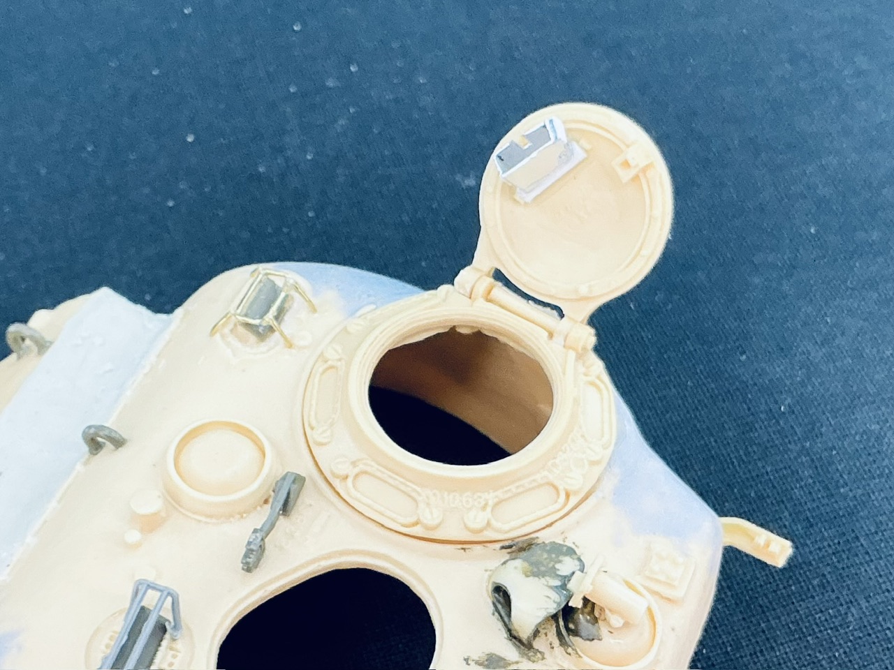
Making the brush guard over the gunner's periscope was a "fun" job. It's about the same size as the others, but the legs are completely different. For strength, I first drilled holes and glued overlong pieces of brass rod in them:

IMG_1917.jpeg


Next to the turret is the rectangular part that will go horizontally between those legs. After the glue on them had dried, I bent the legs inward and glued the rectangle between them:

IMG_1918.jpeg


Though that sounds far easier than it actually was … If I had better soldering skills, I think I would have done well to solder the legs to the rectangle and then bend them to fit the holes I drilled in the turret. But I can't solder all that well, so I had to use superglue instead. Once that has thoroughly dried tomorrow, I'll cut the legs down to the level of the rectangle.

It may appear like the rectangle is leaning backward, but that's an optical illusion in the photograph. It is actually horizontal relative to the turret roof.

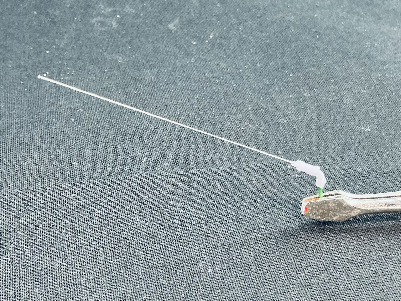
I've also made an antenna:

IMG_1919.jpeg


The base is by MIG, 3D-printed. I drilled a hole into it at both ends: in the top for 0.3 mm spring steel, 52 mm long to represent two antenna sections, and in the bottom for 0.8 mm florist's wire which will go into a corresponding hole in the turret roof. That 3D-printed resin is not a nice material to drill with a bit as small as for the antenna, it's pretty hard and you can only go very slowly.
 
Trimmed to size with my cheap cutters* that are specially designed for thin copper wire:

IMG_1921.jpeg


The commander's hatch is also done, so I glued that in place too.

* A few years ago, in a store selling second-hand tools I came across some cutters costing €20 — a lot of money compared to the other cutters there. They seemed like good quality, though, so after some consideration I decided to purchase them. I got a bit of a start when I looked them up online.
 
As an Amazon Associate we earn from qualifying purchases. Product prices and availability are accurate as of the date/time indicated and are subject to change.
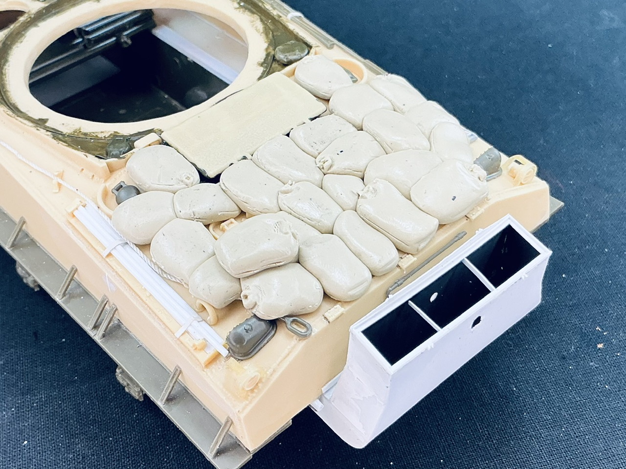
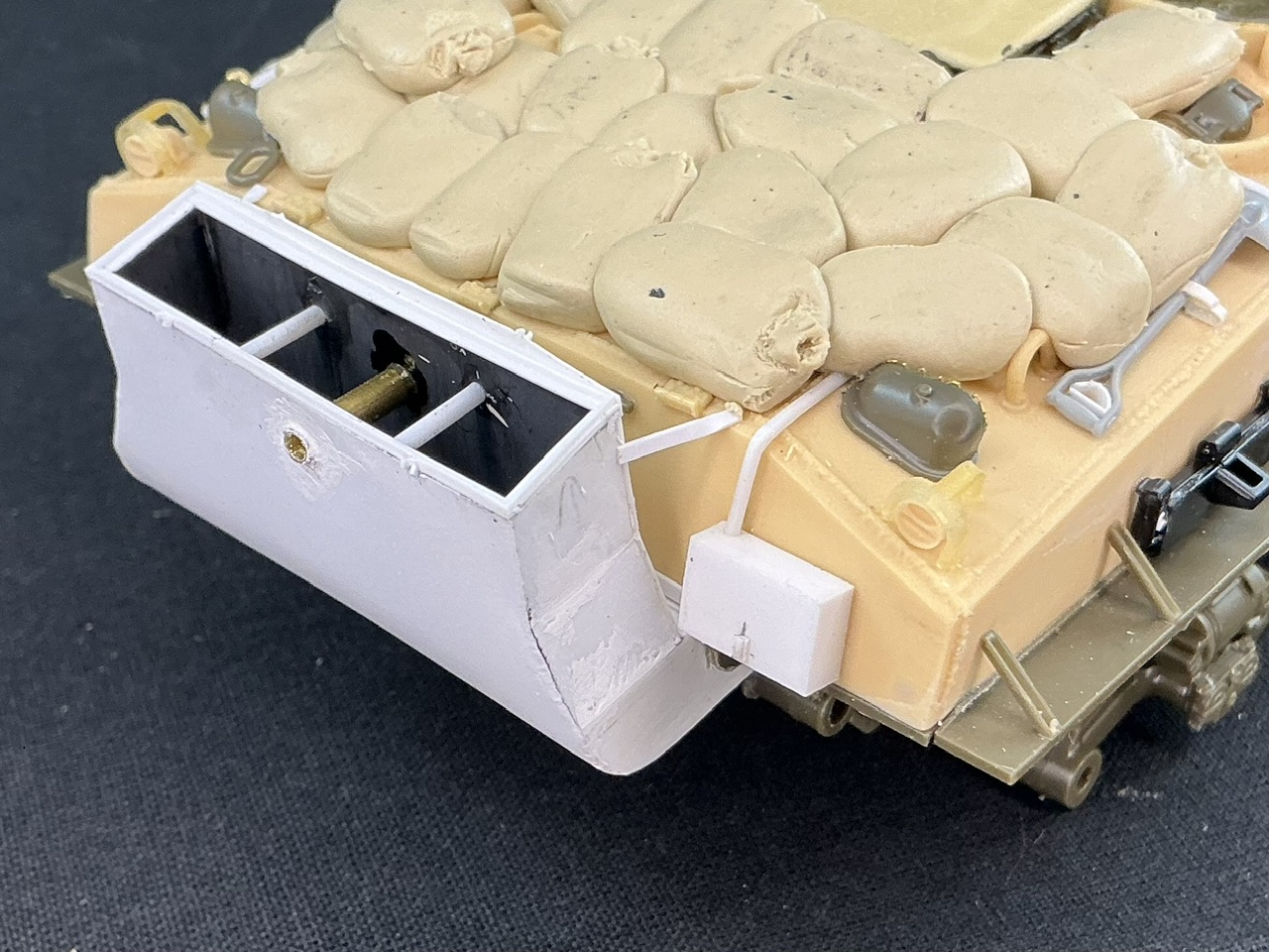
The real tanks had sandbags covering the engine deck, so mine now has too:

IMG_1923.jpeg


These were made from Sylmasta A+B putty, and for the first time in my life I had mixed up exactly enough :)

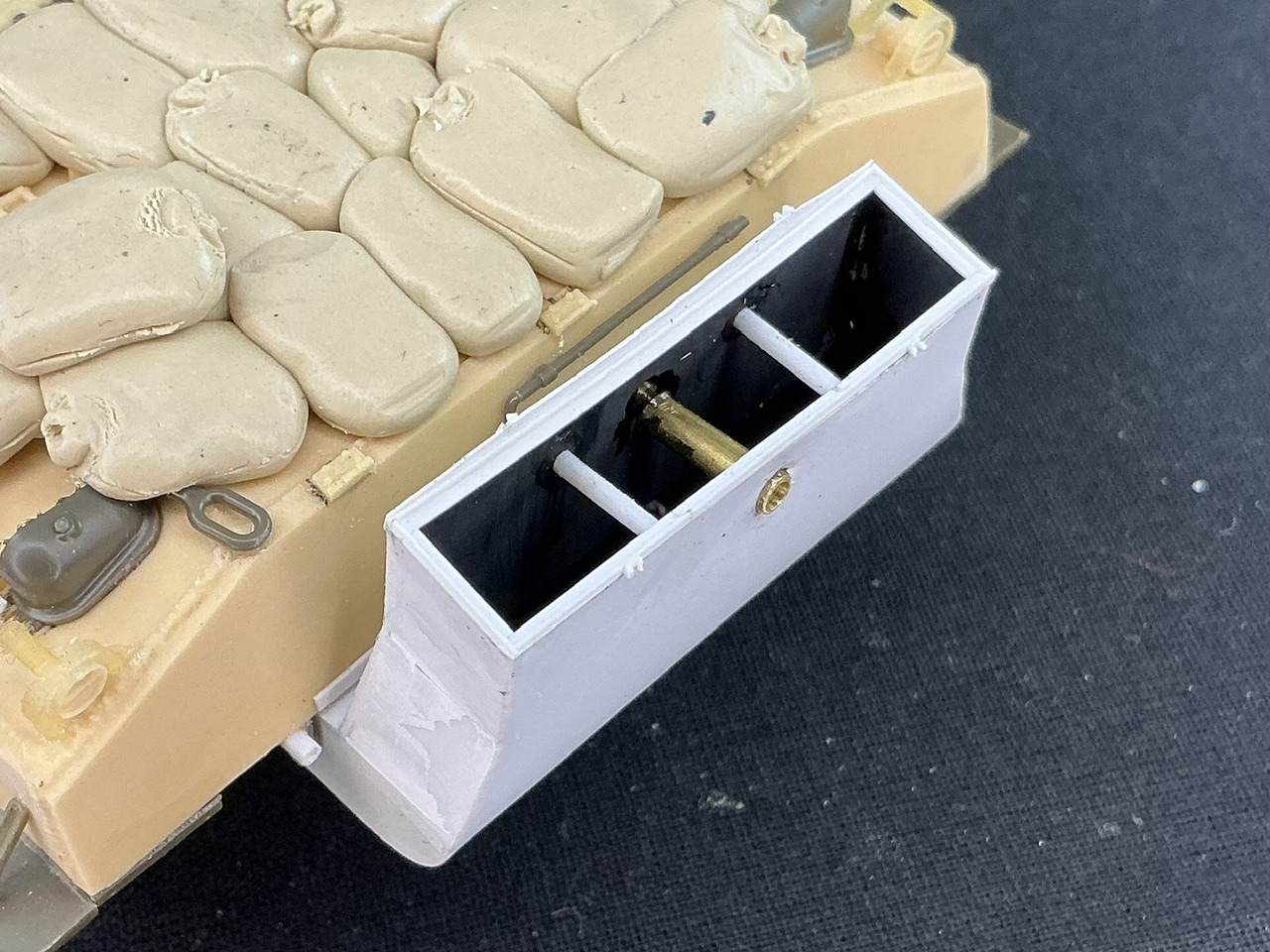
I also made hole in the back and front of the exhaust duct (though slightly larger than I intended to) because today I noticed it on a photo of the real tanks. It answers the question of, "How did they start the tanks when they had that thing attached?" (Because the radial engine in the M4 and M4A1 needed to be hand-cranked for four revolutions before starting, using a crank stuck through a hole at the top of the upper rear hull plate.)
 
The wading gear problem is now solved, too:

IMG_1928.jpeg


Looking even closer at the photos of the real tanks, it's clear that there was a piece of tube in the wading duct. I sawed a length of 2.4 mm brass tube and opened up the inside a little with a round file, then glued it into the duct. I also removed the two bits of strip in the upper opening of the duct and replaced them by some rod a little lower down, because though the strips were there on the M4A3 duct, they were not correct for the M4/M4A1.
 
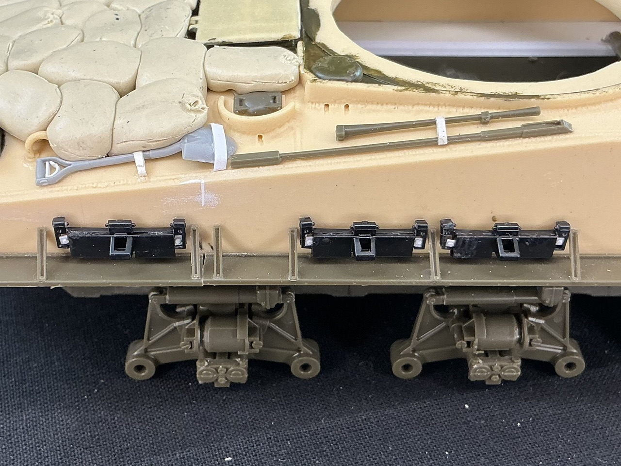
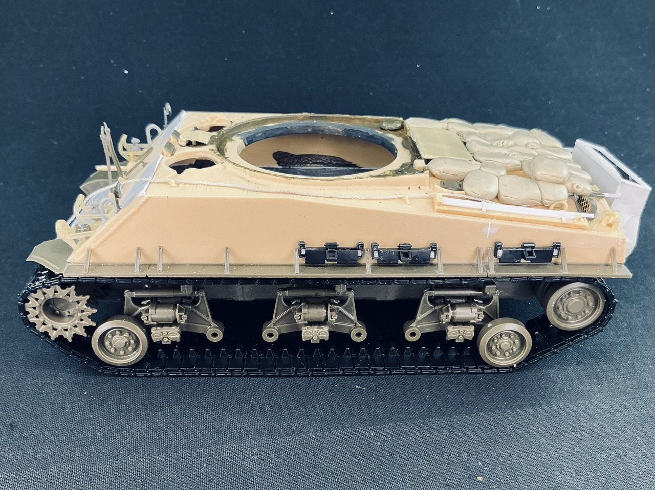
By now I've cleaned up all of the track parts (two per link), and then put the spare links onto both hull sides:

IMG_1931.jpeg


Each of the six sprues has one link in a certain corner, which didn't come out of the mould wuite right: the eye is torn on one side, the same on all six of these links. I therefore used these for the spares, with the retaining clips made from some plastic strip and a punched bolt head.

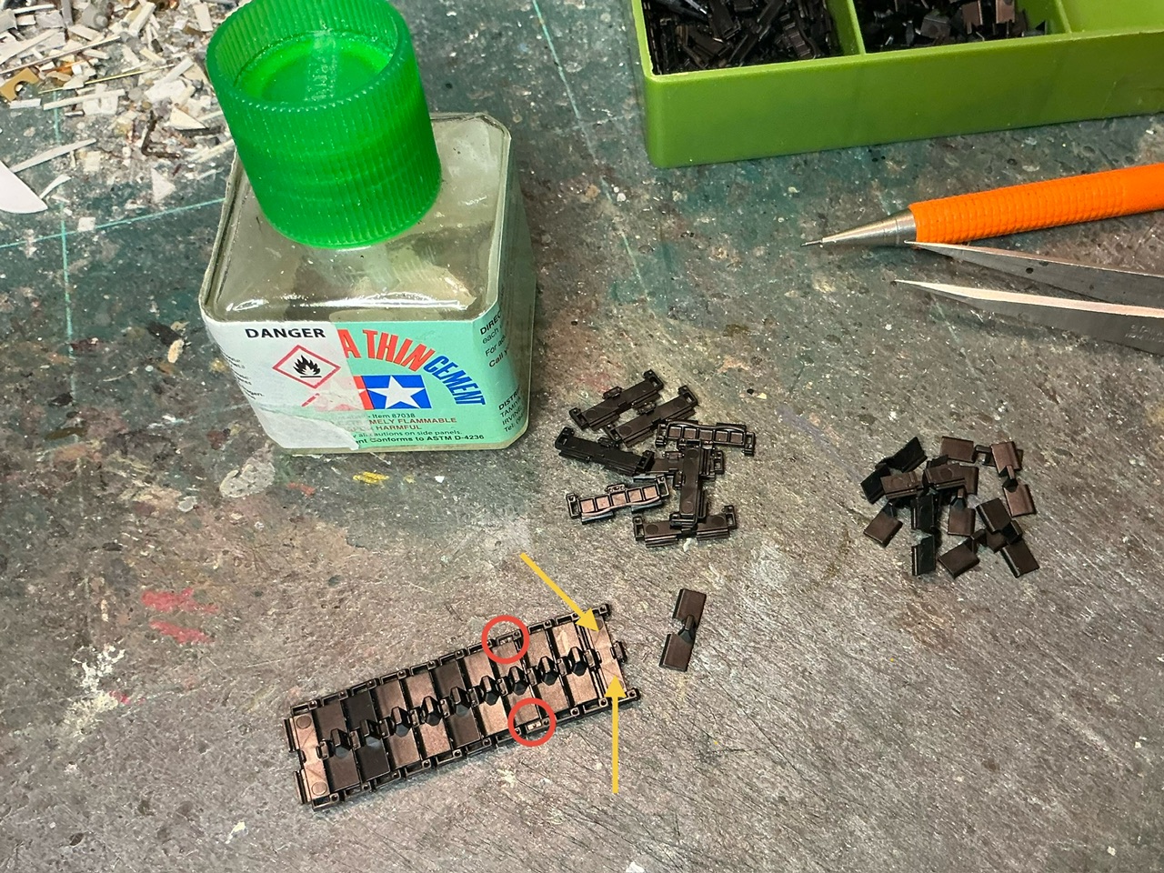
The track itself is easy enough to build: just put two outer parts together so that the pins on one fall in the groove on the other, then glue the inside on. Put a drop of glue where the yellow arrows point to:

IMG_1930.jpeg


… and then press the inner part on — taking care that it's the right way round, because it can be put on in reverse. Also be careful not to use too much glue, because you don't want it running to the pins.

By the time I had just about doubled the length of this section, I noticed that one link came loose. That proved to be because there were no pins on it, and on closer inspection, I noticed the things I circled in red … Each sprue turns out to have one spare link that already has the retention plates I made myself :? Luckily, the glue wasn't dry yet so I could get it out and replace it with a normal link.

In the past, I've also built this type of track from Trumpeter, and found those easier to put together (links in one piece, with pins you push in from the sides) but these Asuka ones have a hollow guide tooth that Trumpeter's lack (but which is hard to see). On the other hand, Trumpeter's tracks don't need any glue, so you can't accidentally stick two links together. I don't think I have a preference for either of the two for a future model.

For the back of the hull, I've also finished the blanket rack:

IMG_1933.jpeg


It's resin, and judging by the paperwork I got with the pile of Sherman parts, it's by Formations. However, it's lacking the stowage for the gun-cleaning rods. That's not wrong, because it was only present on later Shermans, including all 105 mm HVSS tanks, both M4 and M4A3 — though on those, it didn't hold any cleaning rods, because those were carried to the left of the engine deck. Since the main reference picture I'm using of these tanks on Okinawa show the empty rack, I added it from some plastic strip.
 
The final stretch. On the glacis plate, I added mirrors, I think from an Italeri Sherman (I'm sure about the Italeri bit, not about that they came from a Sherman) and also the barrel support:

IMG_1934.jpeg


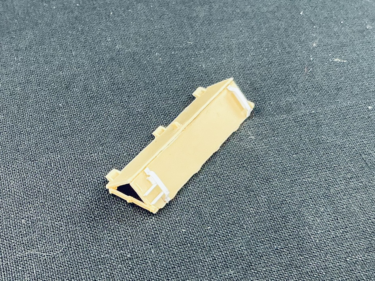
In the main photo I've been basing this model on, I noticed there was a box on the right rear plate, most likely for an infantry telephone, and from shadows etc. I could make a reasonable estimate of its size:

IMG_1935.jpeg


This one is made from rectangular plastic tube with plastic card ends and a bit of plastic rod to represent the tube for the lead to connect it to the tank's intercom system. That tube is completely speculative, because you can't see it in the photo at all due to being obscured by the wading trunk, but something like it must have been there.

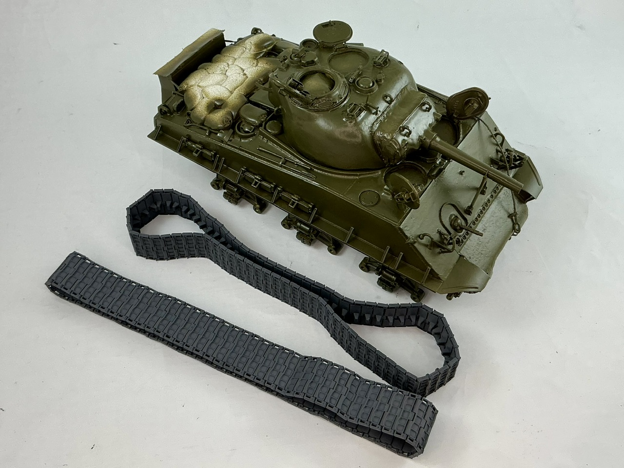
And I finished one track:

IMG_1936.jpeg


77 links, Asuka tells you you need in the instructions for one of the kits that includes these, and that seems to be correct. I did have to glue two roadwheels onto their axles and stick them onto the tank temporarily to work this out, though. Now I just need to make the other one, but the links go together well, so it shouldn't take too much time and effort.
 
I've also made an antenna:

View attachment 131224

The base is by MIG, 3D-printed. I drilled a hole into it at both ends: in the top for 0.3 mm spring steel, 52 mm long to represent two antenna sections, and in the bottom for 0.8 mm florist's wire which will go into a corresponding hole in the turret roof. That 3D-printed resin is not a nice material to drill with a bit as small as for the antenna, it's pretty hard and you can only go very slowly.

I'd like to know, kind sir, how you go about drilling in this situation? I.e. do you clamp the piece, do you use a pin vise...
I find I'm more accurate if I 'use the force': that is to say hold the piece in one hand (perhaps secured in self closing tweezers), and the drill bit, if super tiny, or the pin vise in the other hand; then find a registration mark i have made with the sharpest awl or push pin i could find.
In the end, it just seems that I go more by feel than anything...
Please tell me you have a better way!
 
I drill holes with a pin vice, the kind with a freely rotating "rear" that you can brace against the palm of your hand, and hold the part in my off hand. Depending on the part I may use a pin to make a starting mark, but as often as not I find that as hard to get in the right spot as the drill itself … In short, it seems like we use much the same technique :) The main trick, IMHO, is to keep both the pin vice and the part steady so they don't wobble relative to each other, because that leads to holes larger than the drill bit.
 
If I had better soldering skills, I think I would have done well to solder the legs to the rectangle and then bend them to fit the holes I drilled in the turret.
If you were to try using solder I'd suggest assembling the guard before attaching it to the tank. I'm too paranoid to try it myself, so I am only guessing, but I'd be afraid the heat would melt the styrene, at the point where the wire enters the turret at least. You were able to use enough CA but not make a mess, so I think you chose well.
 
I realise I forgot to mention that detail, but yes: I would have soldered it off the model and then bent it to fit in the drilled holes.

A soldering iron wouldn't melt the resin, BTW — it could make it softer, and then you could push it around, but polyurethane resin doesn't melt as such. A soldering iron, BTW, is a good way to soften resin tracks to bend them around wheels :)
 
At long last, I've done some more work on this model. I put a coat of primer on it yesterday, once more cheap but cheerful stuff from an aerosol can from a discount store, but now white instead of grey. I must say I prefer the grey one, as it covers better. Then today, I sprayed H78 olive drab (2) by Mr. Aqueous over the whole tank:

IMG_2650.jpeg


I had already sprayed the tracks grey some time ago.
 
This model has been very much on the back burner, but now the K2 Black Panther is nearing completion, I also continued with this one. After the last photo, I had given the model a wash and drybrush for the usual shadowing and highlighting, and then painted the sandbags and spare track links, and things then languished for a long time.

I had been unhappy with the highlights for a while — they were the wrong shade (Revell 45 Light Olive) and too pale, which meant the tank's colour no longer looked like olive drab. The other day, I re-drybrushed the model with Humbrol 159 Khaki Drab, which makes the tank look brown-green again instead of grey-green.

IMG_3857.jpeg


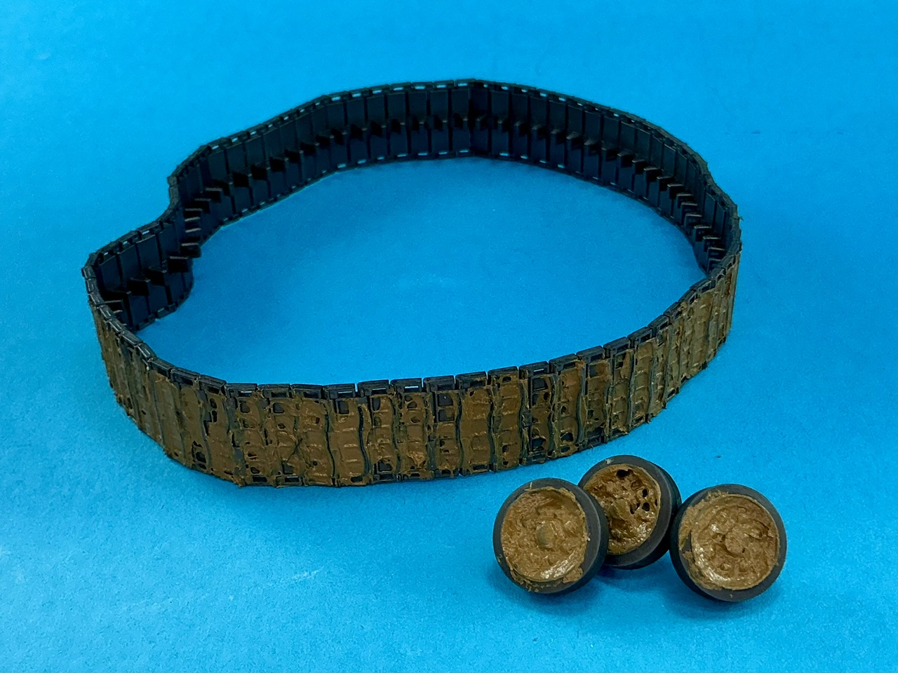
Then today, I treated the wheels and tracks to some peanut butter:

IMG_3858.jpeg


Or, well, it certainly gives that impression :) It's actually acrylic gel medium mixed with Revell 82 Dark Earth — some research last year into the soil colours on Okinawa has given me the impression that this is a reasonably good match for that, straight from the bottle. But once you've mixed it and start smearing it onto your model, it's just like peanut butter (other than the smell).
 
...I just realized that I had just started following this thread when I became active dec '24... then lost track with so much going on.
Is it still on the back burner?
I have an unfinished kit that was put away around 1998. That is not the back burner, not the back 40. That is back-century!

Let's just say the product was not as good as the box-art...
1770857402306.png
 
Last edited:
If you would like to try some, let me know your address and I'll put some in the mail ;)


No, I just got back to working on it :)


I have plenty older than that … And worst of all, I still know what the plan was for them.
Plenty older and started??
 
Plenty older and started, yes. Some completely built and painted, just awaiting a diorama that will never be built now. Others are not even halfway built, and anything in between.
 
Plenty older and started, yes. Some completely built and painted, just awaiting a diorama that will never be built now. Others are not even halfway built, and anything in between.
Why is that? I mean when I start one, I complete it (trash it if don't like), but don't have 1/2 built... On the other hand, I am still young to this hobby.
 
My usual reason is that they've taken so long that I've started to lose interest, combined with something more interesting coming along :) I can't work too long on the same thing, because I get bored once the challenging or interesting parts have been completed.¹ What I can do, though, is return to things I started and work on them some more, and that eventually leads to the thing being completed. Or, of course, it will end up as never finished, because there's quite a lot of stuff that I have mentally filed under "historically unfinished" — which means that I consider its unfinished state to be the way it will always remain, as I have an aversion to disturbing historical artifacts² :)

¹ People have tried to make me do assembly-line-type of jobs more than once. These have invariably lead to me eventually (after some months) walking out very angry and even more frustrated with the stupidity of it all, that built up over time.

² If you hand me, for example, a pile of photographs from decades ago, I will go through them in order and will ensure they remain in that order, including making sure that they keep facing the same way in the pile.
[/hr]
 
Last edited:
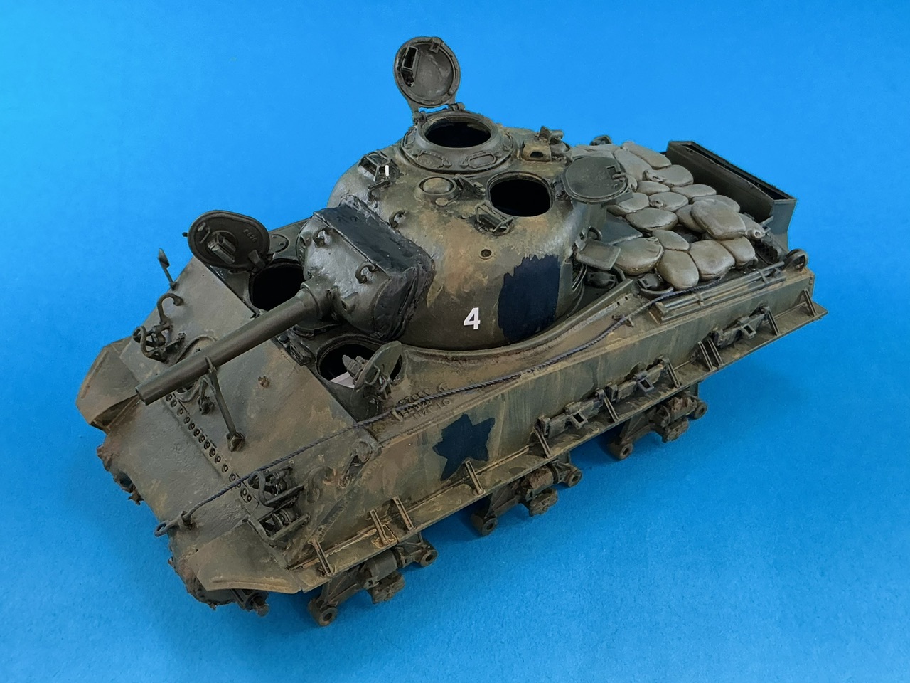
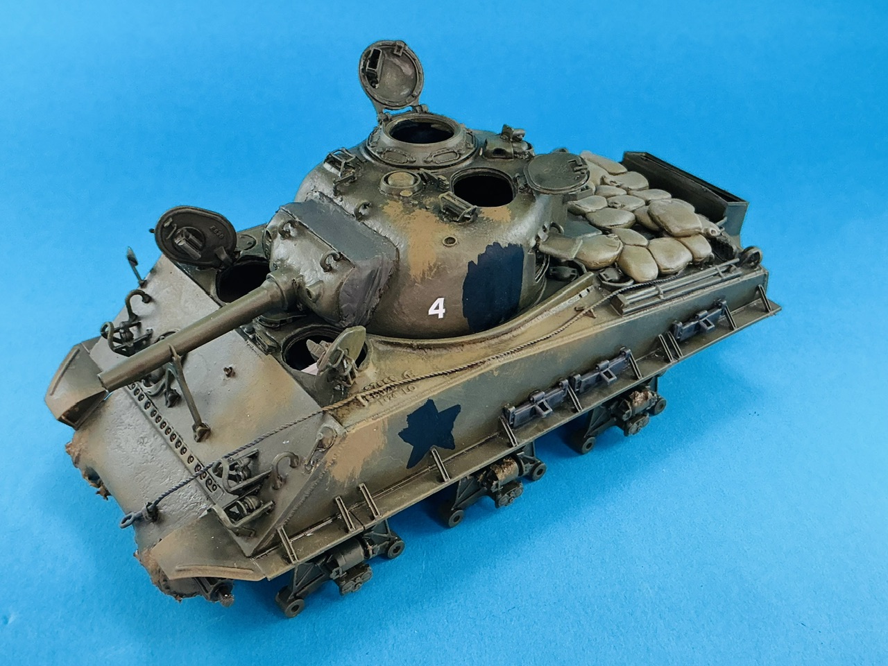
More mud over the whole tank. I first applied Revell Dark Earth with a big brush (something like 7–8 mm diameter, but with the bristles cut at an angle), mainly in the places where you can see mud on the real tank in the photos:

IMG_3860.jpeg


I also added black blotches where the stars should be, and found a suitable number 4 in my box of spare markings. Once all that had dried, I added a wash of the same Dark Earth:

IMG_3872.jpeg


We're not there yet by a long shot, the mud looks fairly pale in colour on the real tank, so this needs lighter colours added. I'm not sure how yet, but as always when dirtying up a model, it's something I'll work out as I go along :)
 
IMG_3873.jpeg
IMG_3874.jpeg


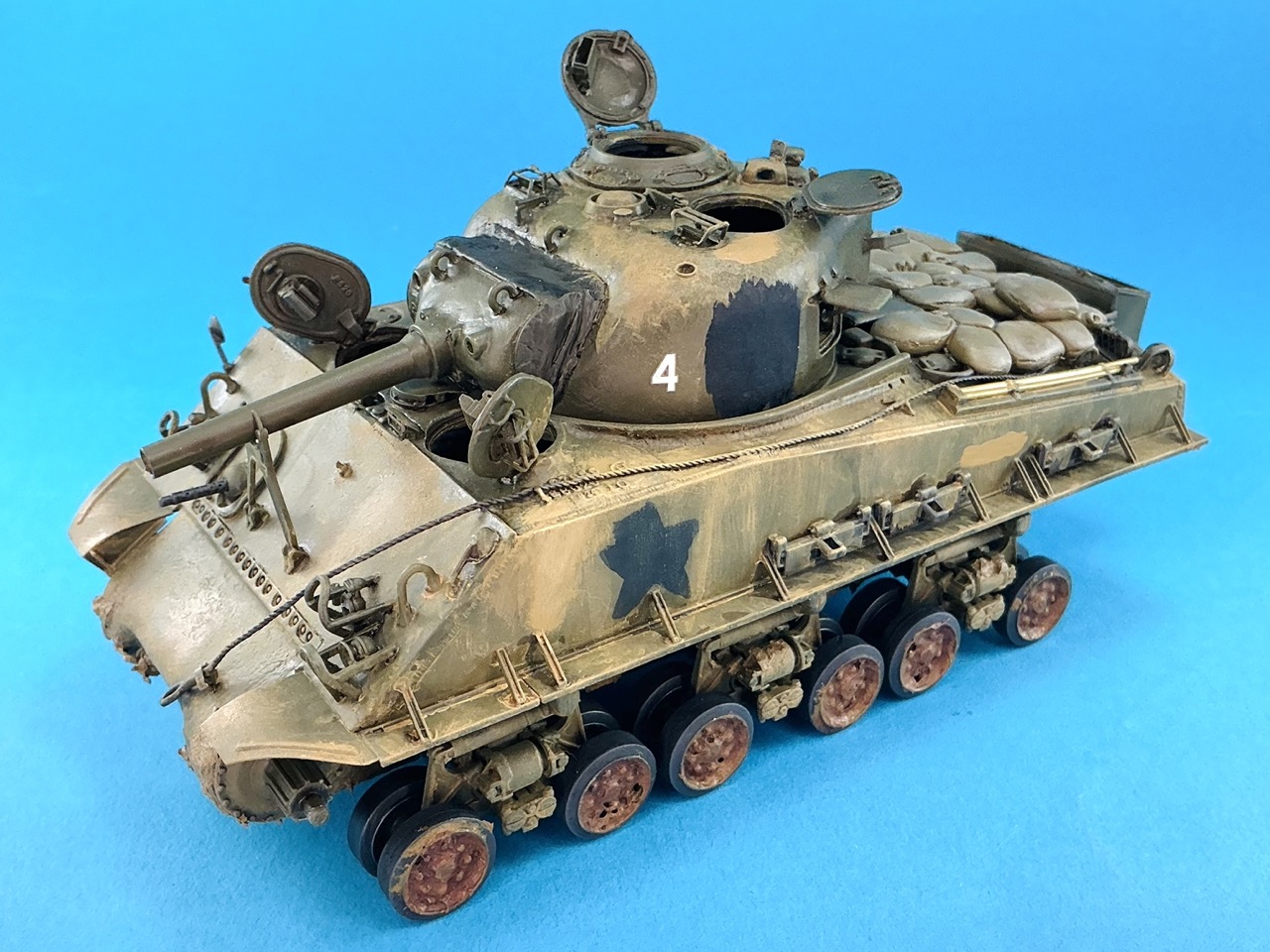
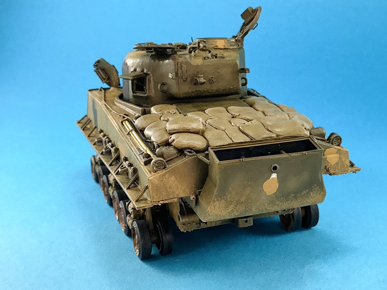
I enhanced the mud stains with two lighter shades of yellow-brown: first AK 3d Gen RAL 8000 Gelbbraun (yes, Afrikakorps sand colour) and then Italeri Giallo Mimetico 3 (an Italian aircraft colour) which noticeably lightened the mud and makes the model look much dirtier. I also installed the roadwheels, after giving them a wash with Army Painter Oak Brown, which is a dark red-brown. This because the mud inside the wheels in the photos of the real tanks seems much darker than that on the rest of the tank. I also used the RAL 8000 to paint blotches on the rear and stripes on the sides where it looks like mud was put over markings.
 

Latest posts

Back
Top