Prototype S-foil positioning mechanism - X-wing

Hagoth

Active Member
Joined
Mar 11, 2015
Messages
492
Introducing my current project. An upgraded S-foil positioning mechanism for my ancient 1:48 scale MPC X-Wing. As a kid I though it was pretty cool even though it is a bit wonky. Now that my engineering side has focused on it there are all kinds of issues. The wings rock independent of the body. They do not open in a synchronized manner and can move independent of each other. You can see through the model side to side and the back and front of the wing box are open. Also, through no fault of the design, the wings are sagging.

I have set out to create a mechanism that fixes all those problems. Here are the results so far.

http://hagoth.wix.com/the-brass-ball#!pm-1a/cjex

While this current project (named PM-1A) is designed for the 1:48 scale MPC X-wing the concept can be adapted to 1:35 scale and 1:24 scale very easily. It can also be easily motorized in any of the scales.

I'm interested in feedback on the concept so far for any scale but especially from those that have the old MPC model (built or not) as this mechanism will likely end up as an upgrade kit for it soon.
 
That's an elegant and smart piece of engineering. Great video - watched it all.

I've built and accurized 3 MPC kits. This would be a nice add-on. I fear the popularity of newer kits such as Fine Molds, Revell and now Bandai might decrease the potential market for this as far as MPC is concerned but as you said, it could be adapted for other kits.

Regardless, fantastic work.
 
Thank you Scott. I appreciate the complement.

As the new 1:48 scale kits come out I can easily make upgrade devices for them if this one does not work for them already. The mechanism will potentially work for a 1:48 scale VII TFA X-wing as well when they release one.

You are right about the newer kits possibly decreasing demand for this particular configuration, however, no matter how many new kits come out there are still many many MPC kits out there with a lot of time put into them that could use the upgrade. As you can see from the video it will be pretty easy to install such a great improvement.

At any rate this will go into my original MPC model for the sake of restoring a little of its past glory and then into a second one with many other upgrades that I still have to build. I'll be posting progress on those conversions.

Configurations for 1:35 and 1:24 are already on the project schedule with a possible addition now for the Hasbro giant toy.
 
By the way, in case there are others that are having trouble figuring out that the last image in the development log is just an image link to the video and not supposed to be the video itself (video link is in the bottom left corner of the image) here is the direct link:

https://www.youtube.com/watch?v=28Q2ZbuiFAc
 
Thank you Quaralane. Nice to have a couple of Overdosed members comment on my engineering. :)
 
Thanks Jake!

I'm not sure of the final production price yet because I have not got that far. Don't freak out but the prototype in the video was about $190 to produce. That's prototype cost. That will not be the price of the final production units. I expect it to be far far South of that mark. I'm currently working on the high resolution parts for creating molds and the manual operating mechanism through the servo hub on the back of the model. Out of the 14 primary parts that make up the unit so far two are proving highly problematic to cast. At least one will need to be produced on a high resolution printer at 16 microns but the cost of that part is minimal so I'm not too worried.

My target is not more than $80- $100 for a complete production unit and as far below that as I can get and still make the minimum amount of profit required to keep this going. I'm trying to keep it so that there is no price difference between the manual option and the motorized version (motor included - maybe) which swaps out the drive shaft and replaces the internal manual servo hub parts with a motor mount.

Now, with that said I will be getting my own 3D printer by the end of the month so my prototyping cost, while still expensive, will drop quite a bit. Some of the more bold may have the opportunity to get a printed prototype copy at cost. Numbered and signed. :)
 
My 3D printer came today! ;D ;D ;D My prototyping cost are going down!

RigidBot Big, dual head, heated bed, USB and LCD. 100 micron resolution. ABS and PLA material on hand and soluble support coming soon. Assembly required. Guess what I'm doing for the next few days.

Project update. The manual operating mechanism through the servo hub plate is designed. I'll post pictures of the renderings by the end of the week.

Do people prefer pictures in the post or links to them off site?
 
Ok, after several hijacks of my time I'm back on track.

Here are the links to my progress on designing the manual mechanism for operating the wings through the servo hub on the back of the model. Any one of the links will allow you to scroll through the other images.

Clutch parts - http://hagoth.wix.com/the-brass-ball#!Manual%20Clutch%20Parts/zoom/cjex/image_i36

Parts installed - http://hagoth.wix.com/the-brass-ball#!Manual%20Clutch%20Parts/zoom/cjex/image_1o5i

Interface with back plate and servo hub - http://hagoth.wix.com/the-brass-ball#!Manual%20Clutch%20Parts/zoom/cjex/image_1w0s

Direct link to video showing operation: https://www.youtube.com/watch?v=IyvSBYLBbtY
There is a bonus feature revealed in the video. :)

Parts are being printed (including a re-print of the messed up high resolution parts) so a complete physical prototype will be coming soon.
 
Thanks! It's those 3:00 AM blasts of inspiration. ;D

This project has been very fun for me so far. Taking it from ideas to reality has been very satisfying.

... especially when it actually works out. 8)
 
While I'm traveling and waiting for the next batch of high resolution parts...

Here are the inside details to the manual clutch part. Yes, I'm revealing some inner secrets but they do little good for anyone without the rest of the mechanism. So... enjoy.

923ada008ed16a.jpg_srb_p_998_531_75_22_0.50_1.20_0.jpg

Here is the cut and paste link to the web site. http://hagoth.wix.com/the-brass-ball#!Manual Drive Cut-A-Way/zoom/cjex/image_1s5u

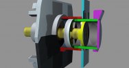
The green clutch and purple hub parts are connected and slide back and forth on the yellow drive shaft through the blue back plate. The sliding clutch is shown half way between snapped in place and engaging the drive clutch. The yellow drive clutch does not move back and forth but rotates once the sliding clutch engages it. The red clutch guide housing is attached to the blue back plate and does not move.

Maybe this will clear up any confusion as to how this is intended to work. :)
 
It's been awhile and it looks like I must have skipped posting about my 1:35 scale Pro Shop X-Wing mechanism on this forum. The video below shows my next step of progress with it and my planned project to do the same with the current production configuration of the 1:48 scale MPC mechanism.

This is an attempt to incorporate the pop in wing root panels that showed up on some of the studio scale models. My goal was to make them fold into the wing mounts as part of the opening and closing action. So, does this capture the look close enough to offer these for production?


Direct link to video
 
Last edited:
Wow that's awesome! How much will they be?

Finally have an answer for you.

1:48 MPC mechanism is $36
1:35 Pro Shop mechanism is $65
1:35 Pro Shop mechanism with folding wing root panels will be $70
...Plus shipping

The units come cleaned of support material and are assembled with micro wires installed for engine lights but are not glued together.
 
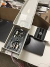
Figured I'd post an update of my latest progress for this project with the MPC scale. Successfully motorized it. Motors are internal and soon so will be the electronics and power supply. Folding wing root panels have been successfully incorporated into the wing mount mechanism. My goal of a completely tether and armature free model X-Wing is nearing reality. Here are some pictures.

Drive unit
IMG_6112.JPG

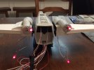
Wings closed with engine test LED's wired up.
IMG_6269.JPG

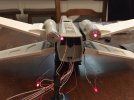
Wings open. Engine light wires are only exposed as engine details in the bay. Otherwise they are completely hidden.
IMG_6270.JPG

Here is a video link of the latest progress efforts: (Direct video posts seem to be unavailable now)

Direct link to video - Part 2

Additional internal details can be found in this video.

Direct link to video - Internal details and concept test

Thanks for stopping by to check out the progress. Hope you enjoy it!
 

Latest posts

Back
Top