Now… Voyager…

I'd like to hear more about your own Voyager build Q. Sounds like you had some real fun eh?

:D

Update...

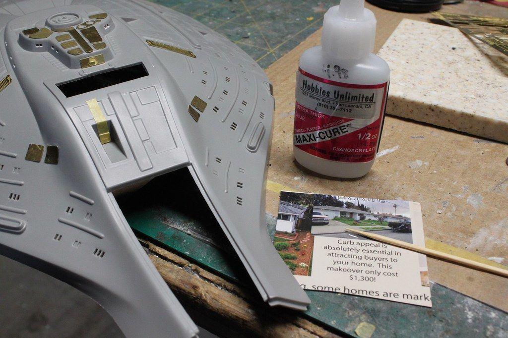
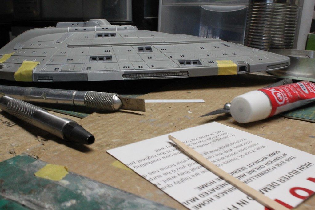
Hobbylinc provided Revell enamel paint tinlets. I write the paint name off the packing slip on the lids using an ink pen.
Most of these are for use on this build.:

View attachment 99897
USS Voyager WIP Img - 017 by Steve J, on Flickr

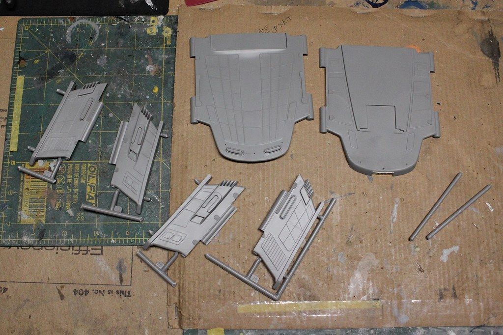
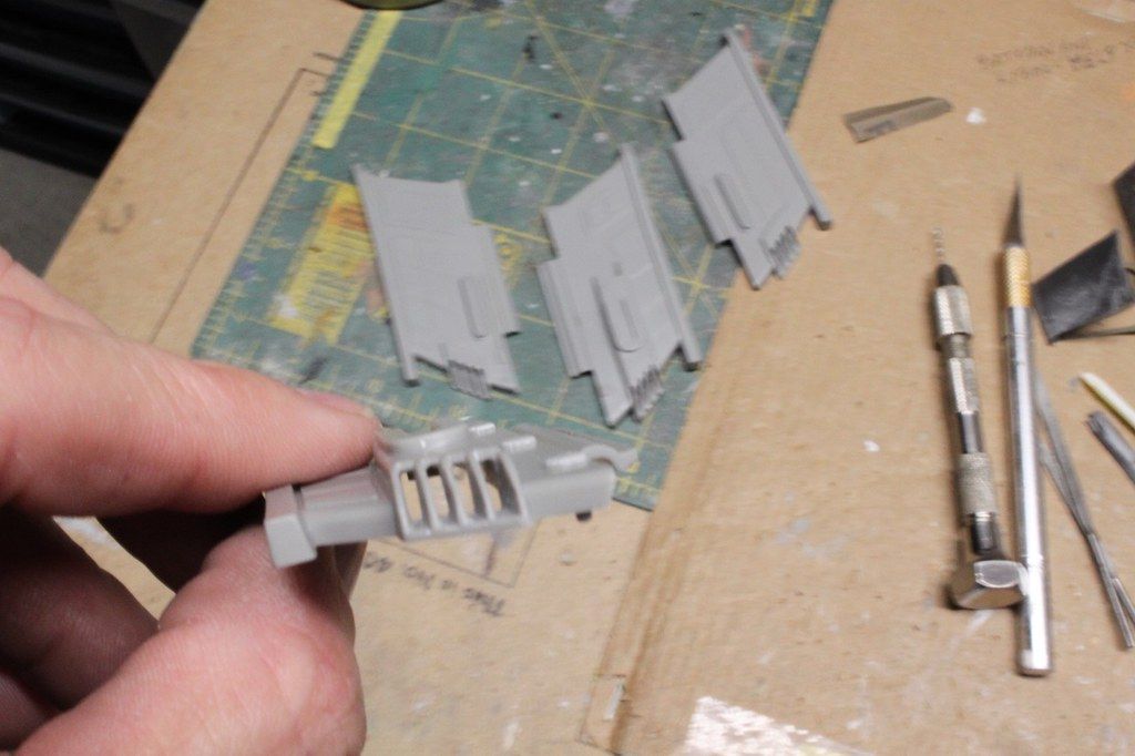
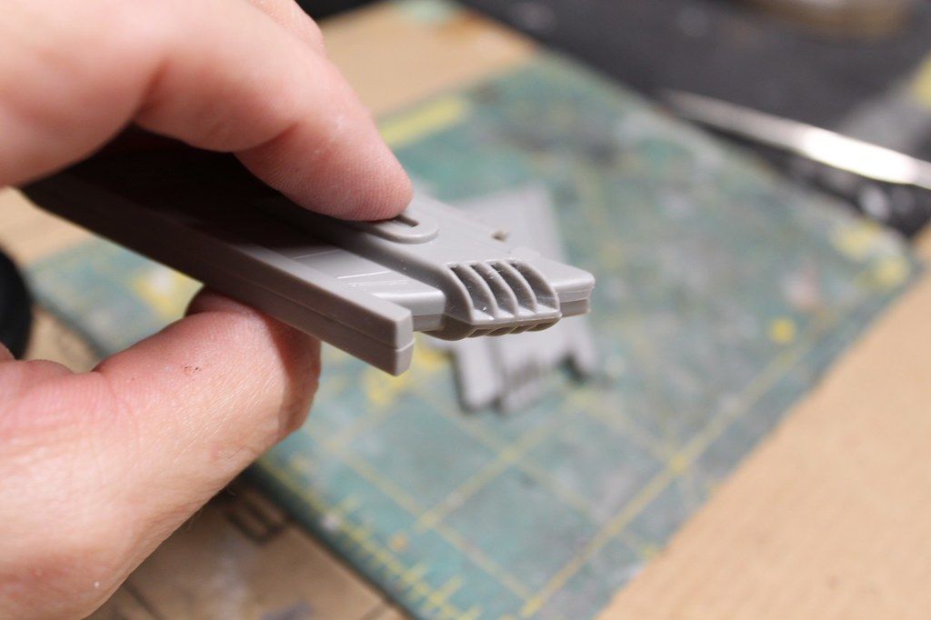
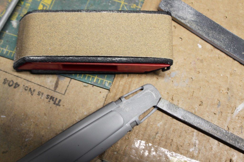
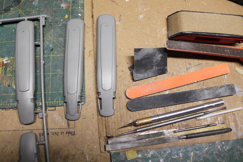
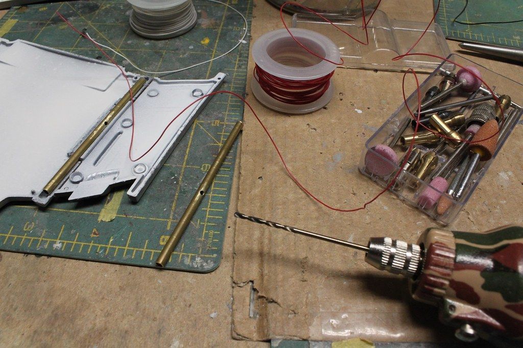
Showing the tools I used to prepare the bridge module for photo-etch panels by removing the kit molded on detail.:

View attachment 99898
USS Voyager WIP Img - 018 by Steve J, on Flickr

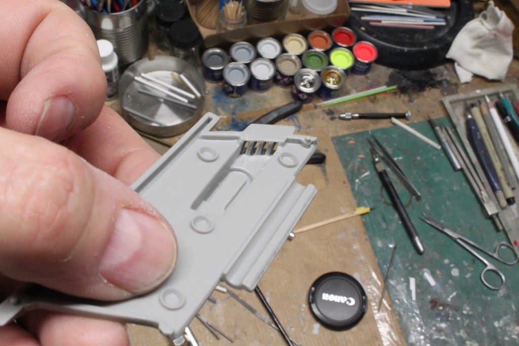
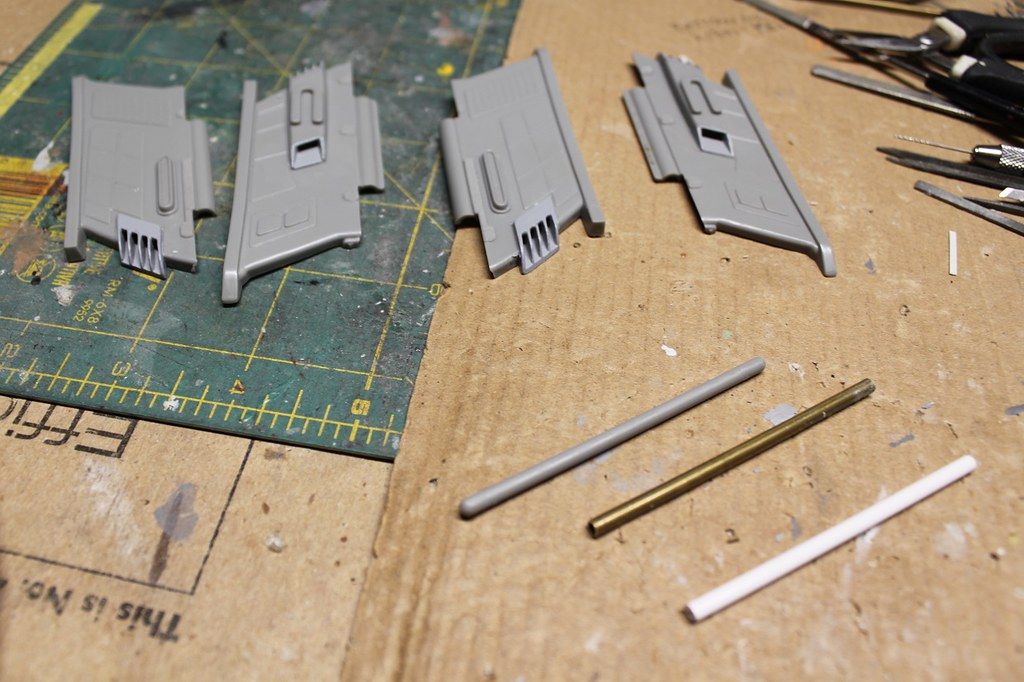
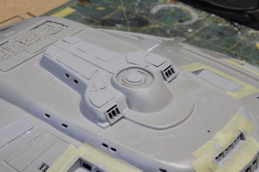
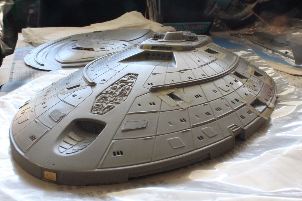
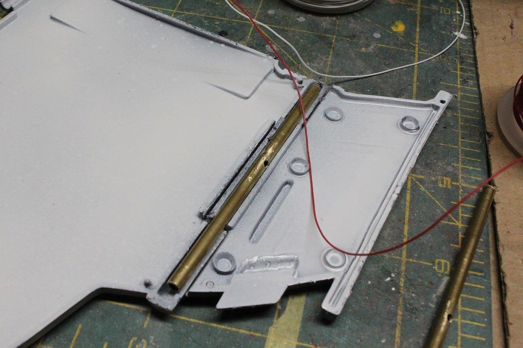
Bridge module after removal of all raised detail on the roof behind the bridge:

View attachment 99899
USS Voyager WIP Img - 019 by Steve J, on Flickr

Light test of some very thin LED strip. This is double density tape and might be a good choice for use in the warp nacelles:

View attachment 99900
USS Voyager WIP Img - 020 by Steve J, on Flickr

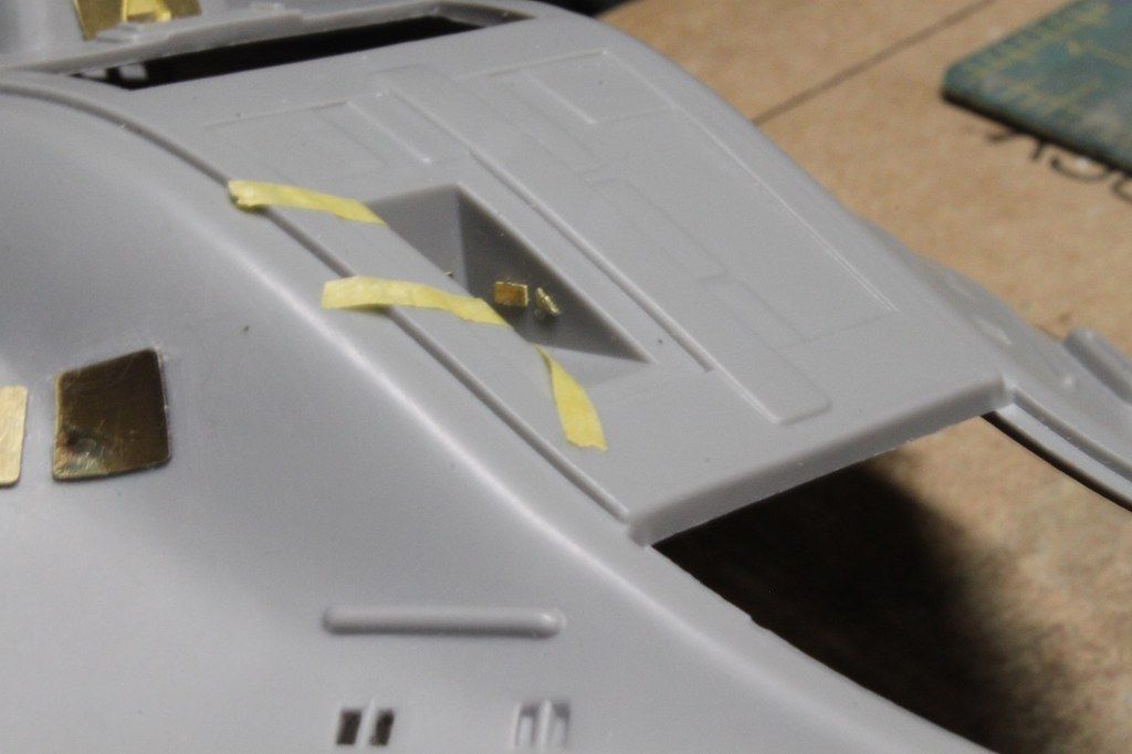
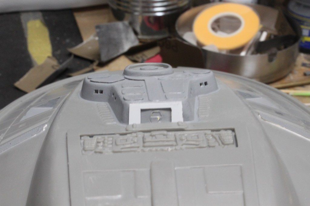
Cut the first piece of brass from the ParaGrafix PE sheet. This runs down the center at the back of the bridge module:

View attachment 99901
USS Voyager WIP Img - 021 by Steve J, on Flickr

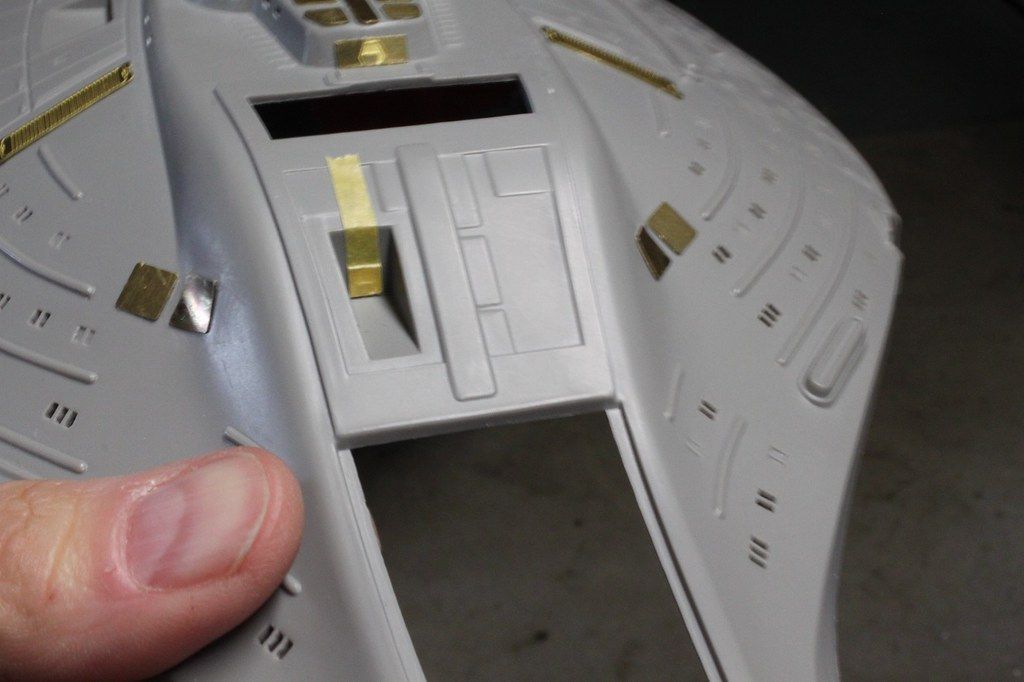
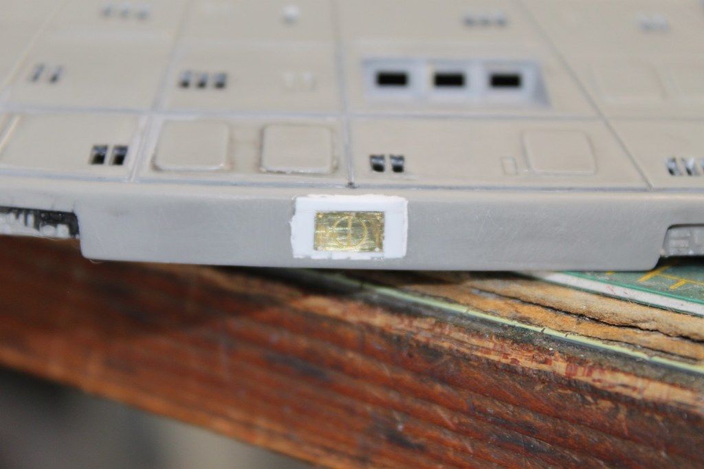
First piece of photo-etch ready to be glued down with thick (10-25 second) CA.
The tape will hold it in position while I smear glue on the underside before pressing it down:

View attachment 99902
USS Voyager WIP Img - 022 by Steve J, on Flickr

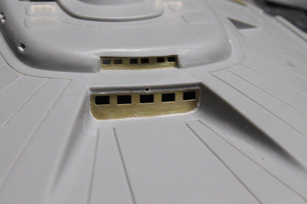
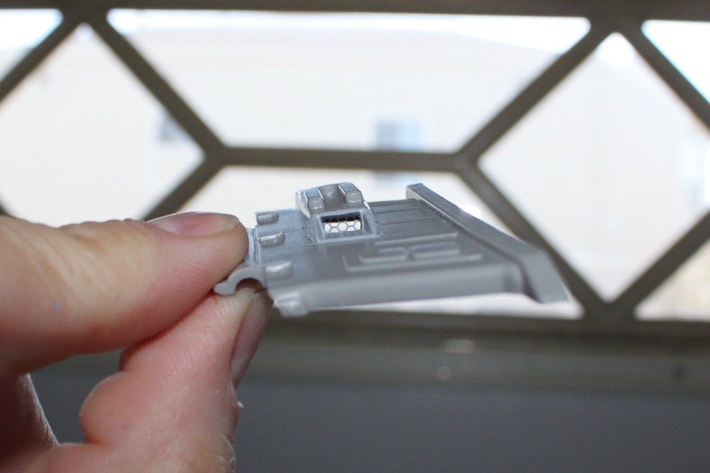
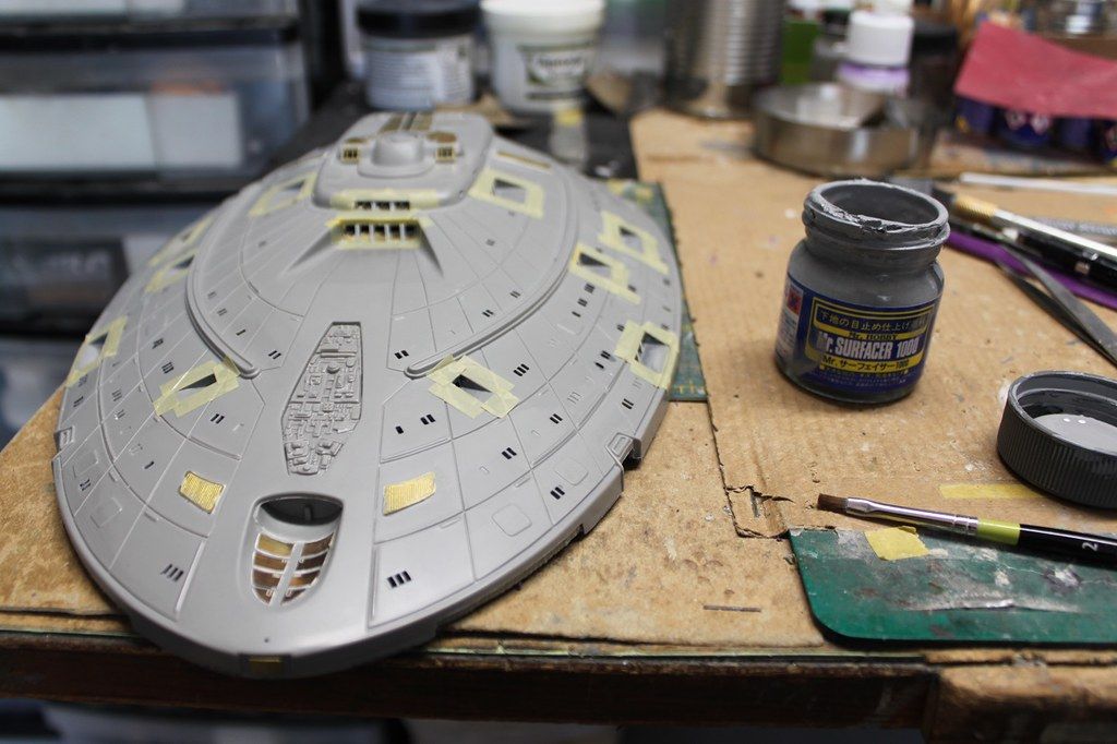
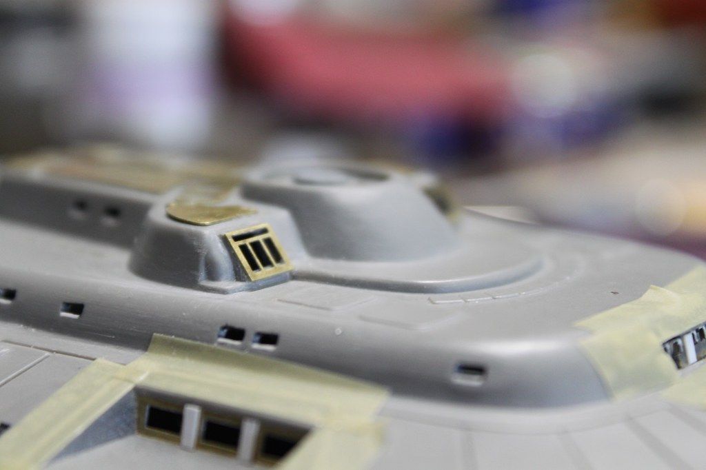
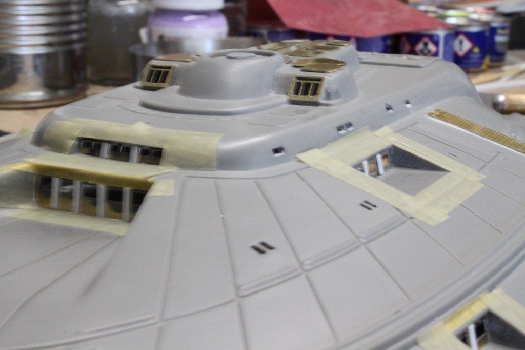
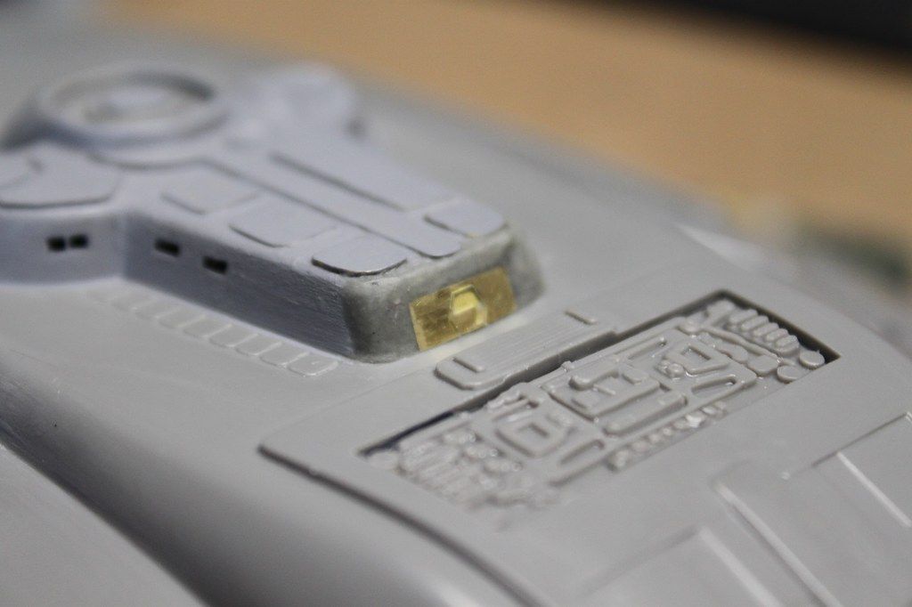
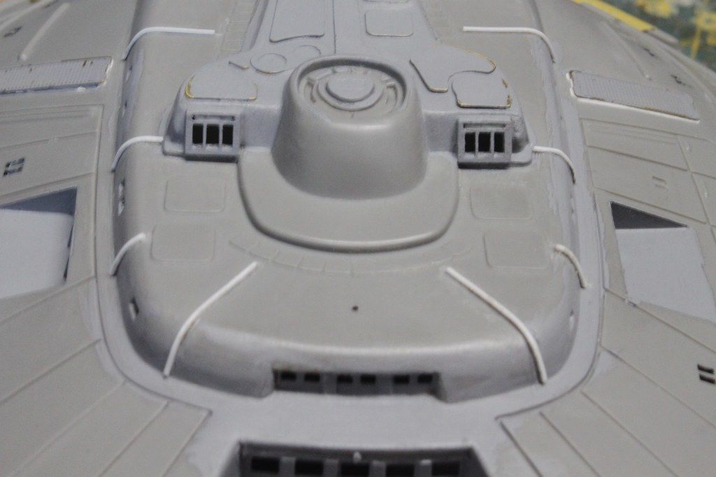
Upper bridge module brass glued in place. I used photos of the Voyager model for help with placement:

View attachment 99903
USS Voyager WIP Img - 023 by Steve J, on Flickr

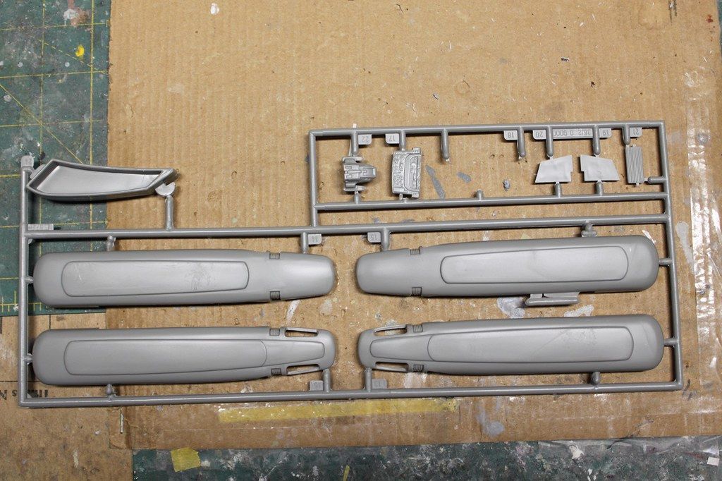
Missing escape pod hatches - port side:

View attachment 99904
USS Voyager WIP Img - 024 by Steve J, on Flickr
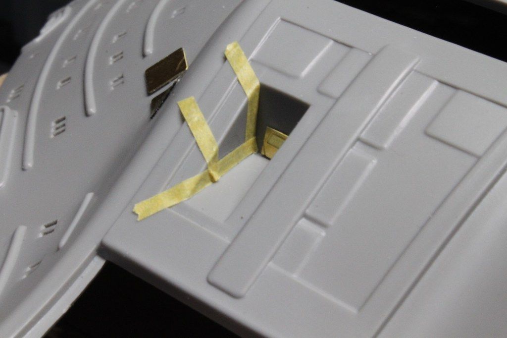
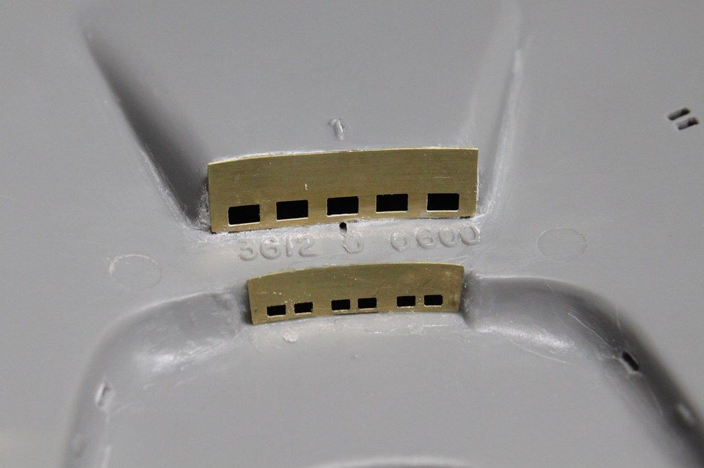
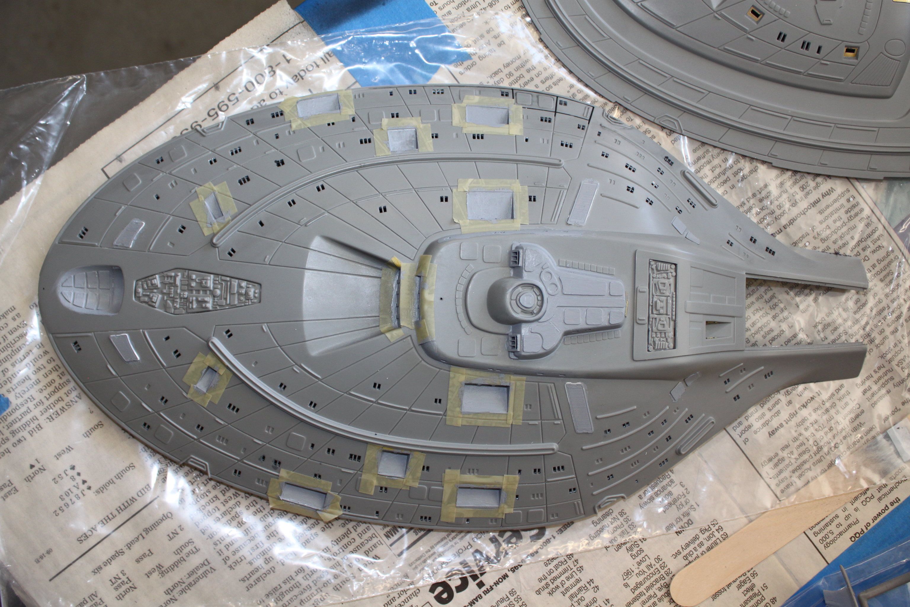
Other side...

Using tape strips makes for perfect alignment:

View attachment 99905
USS Voyager WIP Img - 025 by Steve J, on Flickr

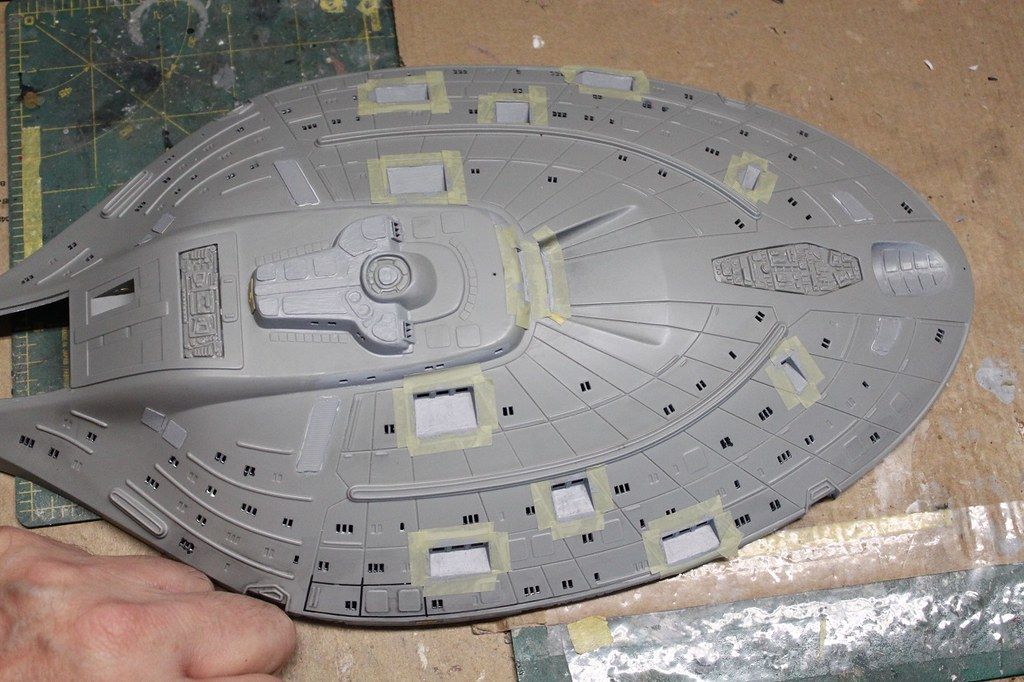
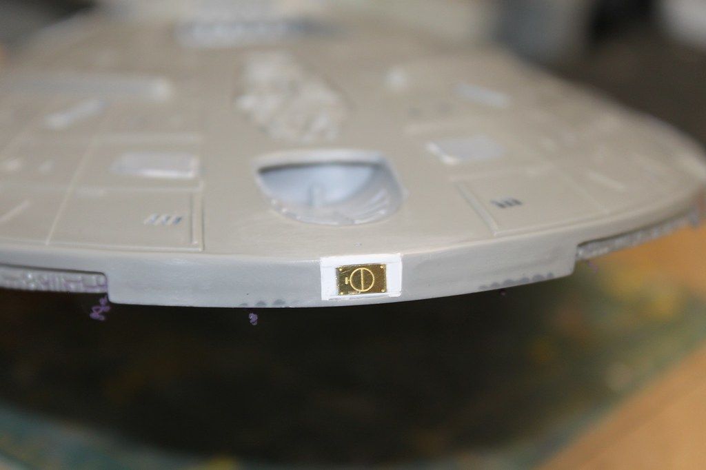
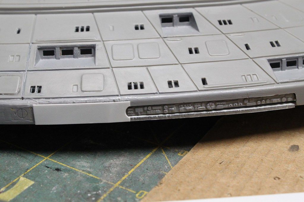
Missing escape pod hatches attached using tape strips for alignment.
I checked CGI and photo references of the studio model and the one door does appear to be curved to match the curvature of the hull:

View attachment 99906
USS Voyager WIP Img - 026 by Steve J, on Flickr

Stay tuned. More photo-etch and drilling fun ahead for all you Voyager fans! :cool:
Great tip for lining up the PE.
Pantherman
 
looks awesome. I built one up probably over 10 years ago now and sadly she was wrecked in a move. i really need to build another. She looks so good all lit up. Nice work on those windows!
 
Rock and roll…

Photo-etch for the forward deflector grids. Tape is laid down for correct spacing and alignment of the bent brass panels:

52853769927_23395de9b3_3k.jpg
USS Voyager WIP Img - 029 by Steve J, on Flickr

To conform to the curve of the trench, I heated the PE using a small butane torch to the point where it became much more bendable.

Pretty happy with how these brass deflector panels turned out. The heat from the butane torch gives the brass a reddish copper look which I like:

52854355231_a9a296eff1_3k.jpg
USS Voyager WIP Img - 030 by Steve J, on Flickr

Upper primary hull window drilling and PE done:

52853769847_ab0e9b65ef_3k.jpg
USS Voyager WIP Img - 031 by Steve J, on Flickr

Upper primary hull window drilling and PE done. Window frames only required some minor CA residue cleanup:

52854800043_ba6c8d4de3_3k.jpg
USS Voyager WIP Img - 032 by Steve J, on Flickr

Window drilling and PE application finished.
Can't wait to try out one of the windows with the back lit panels in position:

52853769602_975a01458e_3k.jpg
USS Voyager WIP Img - 033 by Steve J, on Flickr

primary hull secondary deflector unmasked:

52854799838_dd8c06b143_3k.jpg
USS Voyager WIP Img - 035 by Steve J, on Flickr

Drilling out the lower primary hull windows.
Viewed from interior surface. There were so few windows I went ahead and drilled/filed them all out:

52854745820_b7cac52a9a_3k.jpg
USS Voyager WIP Img - 036 by Steve J, on Flickr
 
And then...

Lower EVA hatch in trench:


USS Voyager WIP Img - 037
by Steve J, on Flickr

Tamiya tape and CA glue for attaching lower EVA hatch PE:


USS Voyager WIP Img - 038
by Steve J, on Flickr

Tape applied for alignment of EVA hatch right trench wall brass panels:


USS Voyager WIP Img - 039
by Steve J, on Flickr

Lower EVA hatch brass photo-etch:


USS Voyager WIP Img - 040
by Steve J, on Flickr

Hole drilled for insertion of fiber optic strand above forward windows in upper saucer hull.
The fiber will look like a spotlight to light the up the ship's upper saucer name and registry:


USS Voyager WIP Img - 041
by Steve J, on Flickr

Hole for "spotlight" fiber optic strand viewed from inside:


USS Voyager WIP Img - 042
by Steve J, on Flickr

Window frame and landing strut cover PE installed in secondary hull:


USS Voyager WIP Img - 043
by Steve J, on Flickr

Aft hull section and wings for nacelles, Will need to rig for wiring as the engines will be lit:


USS Voyager WIP Img - 045
by Steve J, on Flickr

Impulse engine intake vents drilled and filed out:


USS Voyager WIP Img - 046
by Steve J, on Flickr

View from inside after opening up impulse vents and cleaning out any plastic debris:


USS Voyager WIP Img - 048
by Steve J, on Flickr

Next... a bit of serendipity...
 
Impulse exhaust vents looking very clean:


USS Voyager WIP Img - 047
by Steve J, on Flickr

One strut's exhaust impulse engine vents are done:


USS Voyager WIP Img - 049
by Steve J, on Flickr

One strut almost done as far as drilling and carving vents. Still need to open up the intake vent:


USS Voyager WIP Img - 050
by Steve J, on Flickr

Nacelle wing struts and impulse engines. All intake and exhaust vents were brushed with Mister Surfacer.
All the plastic removal I did turned out great after a coat of what is basically thick primer IIDSSM:


USS Voyager WIP Img - 052
by Steve J, on Flickr

Options for the re-positional strut hinge pins shown to the right.
Whichever option I choose will be glued into the wing strut to allow for wiring around a moving hinge joint.
I like the idea of brass tubing but, as with plastic I would need to drill a hole thru one side to feed the wires thru.
Not easy to do with a brass tube but doable.
Plastic hollow tubing would be easier to drill thru but does not have the strength of brass.
I also need to test them in place to see how they play with the raised positioning strip along the secondary hull strut insertion slot.
The strut has a tab shaped to snap into position against another tab in the hull when forced upward for when the Voyager goes to warp.

I drilled and carved out the impulse engine intake vents and glued the Paragrafix PE grill in place from the inside. Then I gave them and the exhaust vents a brushing with Mister Surfacer 1000:


USS Voyager WIP Img - 051
by Steve J, on Flickr

Funny, I didn't notice until uploading this photo how the photo-etch matches my garage door window frames.

Serendipity. Hah!
 
" Funny, I didn't notice until uploading this photo how the photo-etch matches my garage door window frames. "
Ha ha , I thought that was on purpose .
 
Brass tubing will be more durable, have a Dremmel?

Keep the posts coming, this is interesting
 
Need to drill the hole for the aft nacelle formation lights. I'll be using fiber optic strands slaved to red and green LEDs in the nacelles. I also need to size the type of blue LED tape I'll use. I have some really small and thin double density tape I will probably go with, if I can somehow solder the wire leads to it:


USS Voyager WIP Img - 053
by Steve J, on Flickr

I also need to work out how the wiring from the nacelles and impulse engines will feed thru the hinge joint as it traverses the strut into the secondary hull. I have a pretty good idea so will need to try them out.

Nacelle wing halves. Maskol (purple liquid rubber) brushed over areas I want left unpainted, mostly for gluing with Testors styrene cement:


USS Voyager WIP Img - 056
by Steve J, on Flickr

Upper saucer interior lightblocked with black Krylon. Lower saucer sprayed with Krylon gloss white after lightblocking.
The gloss white will bounce light around the interior evenly:


USS Voyager WIP Img - 057
by Steve J, on Flickr

Main part interior surfaces are all sprayed with Krylon gloss white:


USS Voyager WIP Img - 059
by Steve J, on Flickr

X marks the spot. According to Rick Sternbach, the upper nacelle bussard housings did not have a raised panel down the middle on either the studio or CGI models so I will have to remove them using files, sanding sticks, etc:


USS Voyager WIP Img - 060
by Steve J, on Flickr


USS Voyager WIP Img - 061
by Steve J, on Flickr

Plastic removal. One down, one to go:


USS Voyager WIP Img - 062
by Steve J, on Flickr

Masking large window ports for brushing with Mister Surfacer 1000. Prior to this I added structural supports to the window frames using white .010 styrene strip:


USS Voyager WIP Img - 063
by Steve J, on Flickr
 
Working with putty and thick primer before primer spray coat ...

AVES epoxy putty was used to fill in any gaps in the Captain's ready room and conference room window frames:


USS Voyager WIP Img - 064
by Steve J, on Flickr

Super detailing going on:


USS Voyager WIP Img - 065
by Steve J, on Flickr

Upper saucer after brushing photo-etch and adjacent plastic surfaces with Mister Surfacer 1000:


USS Voyager WIP Img - 066
by Steve J, on Flickr

Bridge decks 1 and 2 after brushing with Mister Surfacer.
I also sanded off the little nit on the roof of the bridge leaving it flat:


USS Voyager WIP Img - 067
by Steve J, on Flickr

After Mister Surface brushed on:


USS Voyager WIP Img - 068
by Steve J, on Flickr

Nice angle:


USS Voyager WIP Img - 071
by Steve J, on Flickr

Docking port recesses filled in with styrene strip around brass photo-etch hatches:


USS Voyager WIP Img - 073
by Steve J, on Flickr

Bow brass docking port recess framed with plastic strips:


USS Voyager WIP Img - 074
by Steve J, on Flickr

The rear Deck 2 EVA port PE sat proud of the hull when it should have been recessed.
To correct this I first added AVES epoxy putty to the hull to level it with the hatch, I spent over an hour sculpting and shaping the putty using my dental tools:


USS Voyager WIP Img - 075
by Steve J, on Flickr

To finish the upper EVA hatch detailing I glued a piece of .020 styrene strip to frame the hatch and give it a recessed appearance.
Next I'll use AVES to putty around the strip and make a smooth transition to the hull:


USS Voyager WIP Img - 078
by Steve J, on Flickr

Coming up... working on wing hinges and fixing the rim with strip styrene,
 
FANTASTIC work going on here.
Really brings back memories of my 1978-A buildup of this kit.

Also reminds me of all the work I'm going to need to do on the 1/1000 version
 
FANTASTIC work going on here.
Really brings back memories of my 1978-A buildup of this kit.

Also reminds me of all the work I'm going to need to do on the 1/1000 version
I may have to get me one in 1/1000, the lit version of course.
Be interesting to compare it with this one, I hear it's more accurate to the studio model than the 1/670 kit.
Some inaccuracies of this big kit would be hard to correct for the average modeller.
 
Here we go...

I used my hobby dremel to drill a hole thru the brass tube large enough to pass two pairs of 30 AWG Kynar wire
from the nacelle and impulse engine thru the tube and out the end into the aft hull section and power:


USS Voyager WIP Img - 079
by Steve J, on Flickr

Port wing hinge pin will be glued into the wing's center section of the hinge but not the outer sections of the hinge:


USS Voyager WIP Img - 080
by Steve J, on Flickr

Time for some rimming...

All sensor pallets around the rim will be framed to have rounded corners instead of the kit molded box ends.
The three pod hatches will also be framed to give them a slightly recessed appearance, which is truer to the studio model rather than the CGI images which show the hatches as level with the rim:


USS Voyager WIP Img - 082
by Steve J, on Flickr

I used a leather punch to make the rounded ends of the sensor pallets in 1/4" wide .010 Evergreen strip:


USS Voyager WIP Img - 083
by Steve J, on Flickr

All Evergreen strip has been glued to the upper and lower saucer rim halves using Testors tube glue.
Next I will putty the top of the strip with AVES before sanding the upper rim smooth again.
No seams will be tolerated. Final puttying and sanding won't happen until the hull halves are glued together after I wire up the lights:


USS Voyager WIP Img - 084
by Steve J, on Flickr

Last for today but not least...

I used Evergreen rod to add these structural reinforcement (?) beams to the exterior of deck 2 like on the studio model:


USS Voyager WIP Img - 081
by Steve J, on Flickr
 

Latest posts

Back
Top