Dan the Modeler
Well-Known Member
- Joined
- Jan 8, 2025
- Messages
- 271
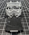
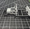
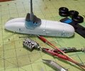
The front firewall sockets need to fit to the front of the lower frame, but they are off by a hair and even the instructions state to trim both sides of the floor frame to get a nice tight fit that is centered. I only had to remove a hair from both sides.
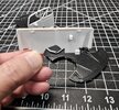
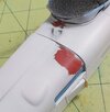
(I'm holding the left socket which is the same as the right. This is what needs to fit cleanly to the lower frame,)
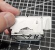
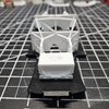
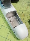
Pictured above is the slight misfit that shows how little you have to remove from the frame to get the firewall sockets in place. After test fits, trimming was done and the firewall fit perfectly and can be glued in place later.
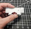
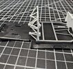
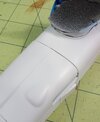
Next the base framing for the motor cage needed to be cleaned up. The frame has seam lines all the way around that are easily cleaned up with the exato.
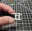
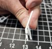
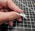
It may be a little hard to see the seam lines above on the all white framing, but it cleans up nicely.
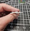
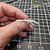
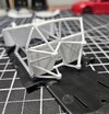
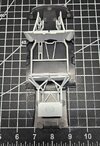
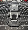
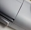
The right and left side motor cage framing was then attached to the firewall bulkhead and set into the under tray to ensure proper alignment.
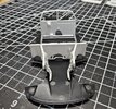
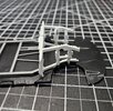
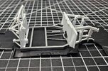
At this point, the front cage has been attached to the firewall, but I still have not glued the firewall to the framing. This will allow me to do the painting that needs to be done to the under tray, frame, and back bulkhead. Then I can attach the front framing. Next, I will be assembling the rear truss and rear chassis assembly. Stay tuned...

(I'm holding the left socket which is the same as the right. This is what needs to fit cleanly to the lower frame,)

Pictured above is the slight misfit that shows how little you have to remove from the frame to get the firewall sockets in place. After test fits, trimming was done and the firewall fit perfectly and can be glued in place later.

Next the base framing for the motor cage needed to be cleaned up. The frame has seam lines all the way around that are easily cleaned up with the exato.


It may be a little hard to see the seam lines above on the all white framing, but it cleans up nicely.


The right and left side motor cage framing was then attached to the firewall bulkhead and set into the under tray to ensure proper alignment.


At this point, the front cage has been attached to the firewall, but I still have not glued the firewall to the framing. This will allow me to do the painting that needs to be done to the under tray, frame, and back bulkhead. Then I can attach the front framing. Next, I will be assembling the rear truss and rear chassis assembly. Stay tuned...

