Leif Ericson Galactic Cruiser

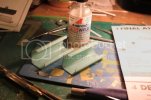
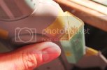
So today I wet sanded the windows to make them level with the hull and decided that 6 or 8 of them looked like crap due to bubbles in the resin when I originally poured from the inside. So I drilled and filled them out, stuck transparent tape on the inside, and refilled them with fresh resin from the outside making sure to drag any bubbles out of the window frames so the resin is nice and clear now. I coudl only do one side of each hull section so will do the windows on the opposite side tomorrow after these are dried. This phase of construction is a pain in the arse but i'm not going to be satisfied with crappy looking windows.
 
Took the day off Friday so got a bit more done...

Step 7:

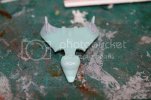
The Scout Ship...

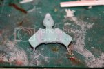
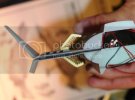
This little bugger has a head like a duck!

IMG_2190-1.jpg

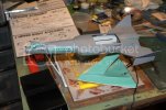
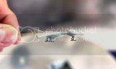
The scout ship is only 4 parts: upper hull, lower hull, and 2 fins.
I won't be using the kit legs as they look loike inverted plastic cups.
I'll be using Paulbo's PE landing gear instead.

After gluing I puttied her top and bottom with Tamiya Basic Type putty.
I'll sand and prime tomorrow:

IMG_2194.jpg
IMG_2193.jpg

Step 8:

The ion drive engines...


IMG_2203.jpg

The engines were fairly easy to assemble.
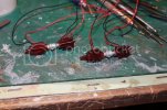
I just fed the wires thru the large slots and inserted the inter-adapters which I'd sprayed with Tamiya silver.
The inter-adapters were a tight fit so had to use a goodly bit of force to get them seated properly so the large clear red tabs on the finned engine bits would align with the slots in the hull.
Then I glued on the intercoolers and spikes.

Step 9:

The stand...


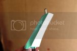
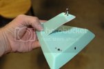
I enlarged the small hole at the top of the stand arm intended for the wires to pass thru from the engines and trimmed away the extra tab that was designed to fit into a slot in the lower hull.
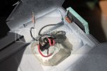
Then I mounted a size K power plug to the top of the stand arm and soldered the wire leads.
After soldering I filled 5 minute epoxy in around the plug threads to secure the plug to the stand arm:

IMG_2197.jpg

I covered the backside of the stand arm with .040 thick styrene sheet:

IMG_2198.jpg

The completed stand.
Still need to sand and paint it of course:

IMG_2200.jpg

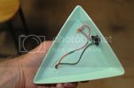
The underside of the stand:

IMG_2199.jpg

I soldered the negative lead to the power jack in the back rim of the base.
The positive lead runs from the pluig in the stand arm to the kit provided slide switch and thence to the power jack.
I figured I'd go ahead and install the switch even though it's rather redundant as the battery box has it's own switch but having the switch in the stand gives me the option of running the model off a wall wart (which doesn't have a switch) if I ever go that route.

I mounted the lower hull to the base and tested the ion drive engines by touching the wires to the power jack wires in the lower hull.
The negative lead from the power jack has a 220 ohm resistor soldered to it.
I was relieved to see that all the lights lit up! Thank God!

Here's a pic of the upper and lower hull on the stand:

IMG_2204.jpg

Next I'll start some of the wiring to light the windows in the forward hull, the neck, the phaser projector, and the commad tower.
I'll also try and finish the hangar bay.
I'm thinking of running fiber optic to the landing lights in the bay.
I want them nice and bright to illuminate the underside of the scout ship as it sits in the bay.
I'm also going to fashion a clear support rod to insert into the underside of the scout ship.
This acrylic rod will have a thin brass rod in the lower end of it to fit thru a hole I'll drill in the center of the circle in the floor of the bay to secure the scout ship.

Thanks for reading!
 
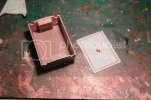
Yesterday I pretty much finished the hangar bay. I glued the side walls and rolling doors in with CA and glued in clear plastic for the side windows. I also drilled a small hole in the circle at the center of the bay for the scout ship support rod. For the floor, the PE had lines inscribed for the basketball court so I took a mechanical pencil and traced along the lines so you can see the markings on the floor. Then I sealed with Glosscote. The only thing remaining are the landing lights which I need to run fiber to.

I also sanded the putty on the scout ship, drilled two small holes-one in the belly and one in the tail giving me two options for inserting a brass support rod, and attached the PE landing struts. So far so good.

I'll post a few pictures later.
 
Update for today...

Pics of the almost finished hangar bay. As mentioned last night I still need to run the fiber to the landing lights:

IMG_2214.jpg
IMG_2213.jpg
IMG_2212.jpg

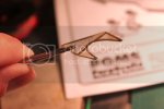
Cleaning up the fret tab on one of the landing struts with a needle file while gripping it with my PE folding pliers:

IMG_2209.jpg

The three landing struts ready for install in the scout ship:


IMG_2210.jpg

Scout ship with landing struts glued in place:

IMG_2215.jpg

More to come... tommorrow!
 
NecronautDrummer said:
Man, your work is always an education in patience and craftsmanship. Hats off to you and another fantastic build log!

Thanks man! Truth be told I haven't gone into great detail at all about some of the mistakes I've made during this build; sufffice to say, it's never as clean and elegant as it seems. I've just gotten real good at fixing my mistakes. Now that I think about it, that seems to me to be what separates the good modeller from the not so good modeller-being able to overcome adversity during construction.
 
The PE landing struts look so much better than the kit struts. That is probably worth the price alone.
 
Had a little fright this morning when I looked at the hangar bay. I'd brushed on some Tamiya flat base onto the floor the day before and when it dried it left a white residue all over wherever my brush had touched which included the floor and some areas on the walls! Yikes!

Not knowing exactly what to do I first tried rubbing the white stuff off with a wet q-tip. This seemed to get most of it off but there was still some left after drying so I then brushed on some Future. That covered most of it leaving only a few small areas of white which, after a second application of Future, are gone now. Once again, Future saves the day!

Question for the members here... Has anyone run into this problem with Tamiya Flat Base? Did I not mix it up enough? Am I supposed to thin it with something before applying it?
 
I believe the Tamiya 'flat base' is meant to be mixed with paint, not used alone as the result is like you mention, a white 'frosting'.
 
Ken Abrams said:
I believe the Tamiya 'flat base' is meant to be mixed with paint, not used alone as the result is like you mention, a white 'frosting'.

Yes. I've heard the same thing from members over on HobbyTalk too. Guess the term "base" should have clued me in to it's intended use. Lesson learned!
 
Today's update:

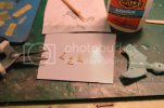
Paulbo over on HobbyTalk reminded me about the hangar bay floor decal that came with the kit.
I had totally forgotten about it!
It will fit in quite nicely around the landing lights.
Thanks Paul!

IMG_2234_zpsa08aeec6.jpg

So last night I spent about an hour working on the engine shrouds.
First thing I did was tape the ion engine in place on the port side afterwhich I taped the hull halves together.
Then I mounted the shroud halves to the hull and brushed on Ambroid ProWeld to the inner seam of each shroud assembly:

IMG_2221_zpsbfe167ba.jpg

Got a nice fit; however, the front of the ion engine was a little too far forward which would place it almost up against the forward PE grillwork so I'll be redoing the slots in the hull where the engine tabs fit so they will sit further back in the shroud.
This will be more in keeping with the position of the engines in the original Leif Erticson kit I built as a boy.
I read somewhere that when they reissued the kit, AMT moved the engines forward, which I don't quite understand since the red plastic fin bits are slotted to allow them to sandwhich the forward inner leading edge of the ship's wings.

After the intial Ambroid set a few minutes I pulled the shrouds off the hull and gave them another going over with Ambroid so the bond was good and strong between the shroud halves:

IMG_2217_zpsafc63c48.jpg

I test fit the forward and rear PE engine grills to the shroud:

IMG_2224_zpsf34c7ea3.jpg
IMG_2228_zps242a200c.jpg

ParaGrafix got the fit just right! Paulbo even accounted for the angle in the forward inner edge at the front of the shrouds by creasing the forward PE where it needed to bend.
Now that's thinking of everything.:

IMG_2219_zpsc8772ace.jpg

The last thing I did last night involved doing something to enhance the glow frrom the ion engine LEDs inside the shrouds.
I remembered I had 2 sheets of 060 spaced corrugated aluminum sheet from K & S Engineering in my hobby cart:

IMG_2218_zpse430ef68.jpg


I'd bought it years ago from HobbyTown for another project but ended up not using it. It was the perfect thing for lining the inner surface of the shrouds:

IMG_2229_zps20ae7149.jpg

The shrouds with corrugated aluminum sheet lining the insides and reedy for priming:

IMG_2231_zps76e60563.jpg

I can hardly wait to see how the engines look all lit up with these shrouds!

Thanks for reading!

;D
 
Thank you my fellow addicts for the kind words!

Updates from yesterday and today...

I finished painting the scout ship and decided to go with a paint scheme very similar to what modelnutz used for his resin kit.
It's so simlar it's almost identical but I really liked the look of his Vega shuttle.
Hopefully he won't mind, after all, imitation IS the greatest form of flattery right?
Anyway, after the paint dried I added some decals from my leftover decal stash to go along with the window decals from the kit.
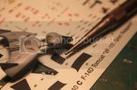
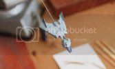
I used a nail set to punch out some tiny round black decals for the four portholes (two per side) on the rear of the pilots cabin:
IMG_2235_zps564a5e31.jpg

Today I gave it a shot of Glosscote to seal the decals:
IMG_2251_zps7314f8f2.jpg

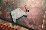
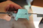
I decided I wanted to be able to turn off the lights in the hangar bay while having the lights in the neck and engines still lit so I canibilized a dollar store booklight for a micro slide switch.
This will allow me to create a separate circuit just for the landing lights and any sidewall and control tower window lights in the hangar.
I cut a slot and installed it in the stern hull bulkhead.
At some point before final paint I'll fashion a slide cover to disguise it better:
IMG_2236_zps111e6d18.jpg
IMG_2238_zps05a87a47.jpg
IMG_2237_zpsa18086a9.jpg

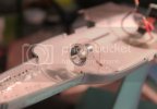
For lighting the neck I used a high brightness (7000 mcd) white LED from Radio Shack.
I installed it facing dead forward mounted in the reflector from that same dollar store booklight.
I soldered a 220 ohm 1/4 watt resistor to the negative leg. :
IMG_2239_zpsfe147a59.jpg

A test in my darkened downstairs bathrooom proved that this one LED is sufficient to light up all the windows in the neck, the command tower, and the phaser projector in the nose.
Pretty awesome IIDSSM!
I thought I might have to add one more near the front but nope, not necessary.

The further along I go with this build the more ideas I get.
One idea actually stemmed from a 3-D mesh Craig Fey did of his interpretation of the Leif.
He added what I would call "impulse engines" to the stern and I thought this looked fantastic!
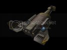
SSC_Leif_Ericsson_WIP8_zps0c3b90bc.jpg

So I just had to do it for my build; however, my engines would be blue rather than yellow...

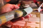
Looking thru my greeblie box I found some transparent blue window inserts I'd saved from some empty Glide dental floss dispensers:
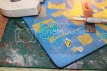
IMG_2240_zps9317add5.jpg

I also use the small plastic hubs that the floss wraps aorund for making shrouds for my LEDs but that's another story.

Anyway, I gave these transparent blue bits of plastic a rough cut using an xacto razor saw blade:
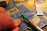
IMG_2241_zpsaebb9102.jpg

Then I filed and sanded them to final shape and placed tham on the hull just for ducks, They looked pretty good I thought:
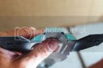
IMG_2242_zps8513441a.jpg

Tracing the shape of the inserts onto Tamiya tape I used them as a guide to drill several pilot holes thru the plastic afterwhich I cut the plastic out with a #11 blade:
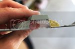
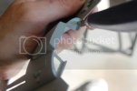
IMG_2243_zps94c2194a.jpg
IMG_2245_zpscf7e94da.jpg

The holes after cleanup with a half round needle file file and my xacto knife:
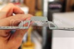
IMG_2246_zpsc3970b7c.jpg

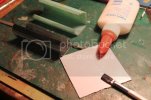
The blue inserts were given a light sanding with a fine sanding stick to make them somewhat more opaque then glued into the openings with Elmers white glue:
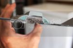
IMG_2247_zpsfccd79b0.jpg

The fit was perfect. No light leaks so no puttying required. This was accomplished thru extensive test fitting while I shaped the holes until the pieces slid in nice and snug.

Here's where I started getting real creative. I'd bought some mesh brass photo-etch years ago before my local HobbyTown USA closed...
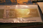
IMG_2248_zps371dbd47.jpg

...and it was just laying around looking meshy and taunting me until I could finally find the right use for it and that time was now! I trimmed two quarter round pieces from the sheet and glued them insode the hull behind the blue impulse engine vents:
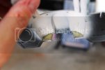
IMG_2249_zpsfd2f1bf9.jpg

It looks pretty cool from the outside don't you think?
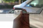
IMG_2250_zps69b66dfe.jpg

Next thing I'll do is install two blue LEDs to light up the impulse engines.
By the way, those Trek purists who may take exception to me calling them "impulse" engines shoudl recall that Matt Jeffereies himself designed this ship and, aside from that, the instruction sheet itself makes reference to the nose-firing phaser projector so the Star Trek connection has been well established by now.


Next up I install the hangar bay and doors in the upper hull and run fiber to the landing lights. Then I'll finish up the wiring and seal the hull.

As always, thanks for reading!
 

Latest posts

Back
Top